Wireguard Peer To Peer Configuration example: Difference between revisions
TautvydasV (talk | contribs) mNo edit summary |
TautvydasV (talk | contribs) mNo edit summary |
||
| (One intermediate revision by the same user not shown) | |||
| Line 11: | Line 11: | ||
==Topology used in this example== | ==Topology used in this example== | ||
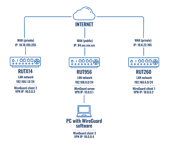
[[File: | [[File:Wireguard peer to peer config example topology v3.png|border|class=tlt-border]] | ||
==WireGuard instance creation== | ==WireGuard instance creation== | ||
| Line 132: | Line 132: | ||
You will see the interface's and its peers' information. In the peer information section look for the latest handshake (a line below allowed IPs). If you can see “latest handshake” it means the peer made a connection to the server. | You will see the interface's and its peers' information. In the peer information section look for the latest handshake (a line below allowed IPs). If you can see “latest handshake” it means the peer made a connection to the server. | ||
This is an example of how the command’s output could look like:<br> | This is an example of how the command’s output could look like:<br> | ||
[[File:WG show output | [[File:Teltonika Networks WG show output v3.png|border|class=tlt-border]] | ||
'''Note:''' if you do not see the latest handshake line, then try pinging the server’s Public IP (the one specified in the Endpoint Host parameter) and/or server’s VPN IP (in this example it would be the 10.0.0.1) from each peer. | '''Note:''' if you do not see the latest handshake line, then try pinging the server’s Public IP (the one specified in the Endpoint Host parameter) and/or server’s VPN IP (in this example it would be the 10.0.0.1) from each peer. | ||
Latest revision as of 08:29, 15 January 2024
Main Page > General Information > Configuration Examples > VPN > Wireguard Peer To Peer Configuration exampleIntroduction
WireGuard is a simple, fast, lean, and modern VPN that utilizes secure and trusted cryptography. This example covers Peer-to-Peer configuration and LAN-to-LAN connectivity using WireGuard VPN.
Note: If you do not see WireGuard in Services → VPN. Go to System → Package Manager → Packages page and install it from there.
Prerequisites
For this example, you will need:
- Three RUTOS devices with different LAN networks
- One RUTOS device will need to have a Public IP address
- An end device with the ability to install, set up WireGuard client, and configure RUTOS devices
Note: remember to switch the WebUI into Advanced mode.
Topology used in this example
WireGuard instance creation
To create a WireGuard interface follow these steps:
- Connect to WebUI
- Go to Services → VPN → Wireguard
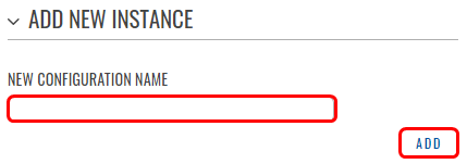
- Enter the interface name and press Add
WireGuard instance general configuration
In this example, each interface’s general settings will be similar for all RUTOS devices. The difference will be in the assigned IP address. To set up the general configuration, follow these steps:
- When you have pressed
 near the WireGuard interface, go to the General Setup section
 - Enable the interface
- Press

- Take note of the interface’s public key
- Set an IP address. For the server set 10.0.0.1/24. For the clients set the IP to 10.0.0.2/24 and higher. For example, client #1 – IP 10.0.0.2/24, client #2 – IP 10.0.0.3/24, and so on
Below is an example of the server’s WireGuard interface:
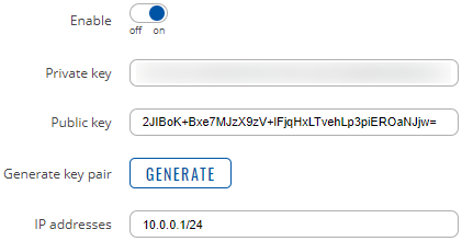
Peers Configuration
Next, we will add WireGuard peers. Go to each device's WireGuard interface and go to the Peers section (below the interface’s general/advanced settings).
Client 1 configuration
To create client #1 to server/peer configuration, follow these steps:
- Enter the instance name (for example, server) and press Add
- As Public Key set the server’s public key. To find it go to the server’s WireGuard interface settings. There you will find the public key
- As Endpoint host set the server’s public IP
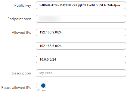
- In the Allowed IPs add IP addresses and networks you want to access. In this example, we will add the VPN network and each peer’s LAN network
- Additionally, you can write the peer’s description
- Enable Route allowed IPs
- Press

The configuration could look like this:
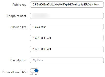
Client 2 configuration
To create client #2 to server/peer configuration, follow these steps:
- Enter the instance name (for example, server) and press Add
- As Public Key set the server’s public key. To find it go to the server’s WireGuard interface settings. There you will find the public key
- As Endpoint host set the server’s public IP
- In the Allowed IPs add IP addresses and networks you want to access. In this example, we will add the VPN network and each peer’s LAN network
- Additionally, you can write the peer’s description
- Enable Route allowed IPs
- Press

The configuration could look like this:
Client 3 configuration
Firstly, ensure that you have downloaded and installed WireGuard client (wireguard.com/install) for your PC. To create client #3 to server/peer configuration, follow these steps:
- Launch the WireGuard software
- At the bottom of the left corner select Add Tunnel → Add empty tunnel…
- In the configuration window add these settings:
Address = 10.0.0.4/32
DNS = 8.8.8.8

[Peer]
PublicKey = Server’s public key
AllowedIPs = IP addresses and networks you want to access. In this example, we will add the VPN network and each peer’s LAN network.
Endpoint = Server’s IP with WireGuard port. In this example, client #3 is inside the server’s LAN network.
The configuration could look like this:
[Interface]
PrivateKey = wireguard-private-key
Address = 10.0.0.4/24
DNS = 8.8.8.8

[Peer]
PublicKey = 2JIBoK+Bxe7MJzX9zV+lFjqHxLTvehLp3piEROaNJjw=
AllowedIPs = 10.0.0.0/24, 192.168.1.0/24, 192.168.6.0/24
Endpoint = 192.168.9.1:51820
Note: do not forget to press Activate to connect client #3 (WireGuard client software) to the server.
Server configuration
Now we will need to add peers to the server's WireGuard interface.
Peer 1 configuration
Follow the steps below to configure settings for client #1:
- Enter the peer’s name (for example, client1) and press Add
- Set the peer's Public Key. To find it go to the client #1 WireGuard interface's general settings. There you will find the public key
- In the Allowed IPs add IP addresses and networks you want to access. In this example, we will add client #1 WireGuard interface’s IP and its LAN network address
- Enable Route allowed IPs
- Press

The configuration could look like this:
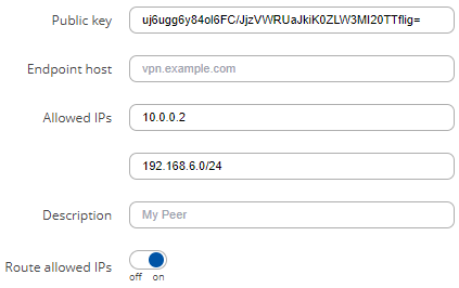
Peer 2 configuration
For client #2 the steps are the same. Remember that the public key will be different and the allowed IPs list will slightly differ compared to the previous configuration.
Peer 3 configuration
Since client #3 is a PC running WireGuard inside the server’s LAN the configuration will slightly differ compared to the other clients. Follow these steps:
- Enter the peer’s name (for example, client3) and press Add
- Set the peer's Public Key. To find it go to the WireGuard software inside the PC. In the Interface section below the Status indicator, you will find the public key
- Set the Endpoint host to the server’s public IP
- In the Allowed IPs parameter add IP addresses and networks you want to access. In this example, we will only add the client's #3 WireGuard interface’s IP. We will not add its LAN network because client #3 is already inside the server’s LAN
- Enable Route allowed IPs
- Press

The configuration could look like this:
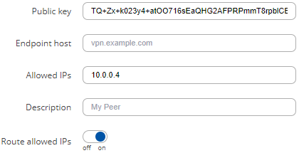
The server interface's peers section could look like this:

Additional Server configuration
After completing the previous steps, now we will need to configure the server’s firewall to allow Peer-to-Peer communication. Follow these steps, to do that:
- Connect to the server’s WebUI
- Go to Network → Firewall → General settings
- Press Add to create a new zone
- Set input, output, and forward to Accept
- Set Covered networks to the server’s WireGuard interface
- Set Allow forward to destination zones and Allow forward from source zones to WireGuard
- Press

The configuration could look like this:
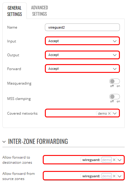
Testing the configuration
Once you have finished the configuration, you can test it by checking if all the peers performed a handshake and if they can reach each other in the VPN network.
Checking for WireGuard handshakes
Connect to the server’s CLI and type
wg show
You will see the interface's and its peers' information. In the peer information section look for the latest handshake (a line below allowed IPs). If you can see “latest handshake” it means the peer made a connection to the server.
This is an example of how the command’s output could look like:
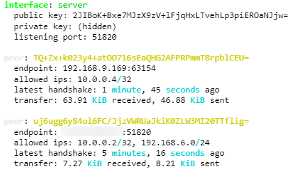
Note: if you do not see the latest handshake line, then try pinging the server’s Public IP (the one specified in the Endpoint Host parameter) and/or server’s VPN IP (in this example it would be the 10.0.0.1) from each peer.
Checking the connectivity between the peers
Access client’s #3 (PC running WireGuard software) CLI. Then try to ping the client’s #1 and client’s #2 LAN networks. The test will be successful if you will see the same amount of transmitted and received packets. This is an example of how successful pings could look like:
Pinging 192.168.1.1 with 32 bytes of data:
Reply from 192.168.1.1: bytes=32 time=119ms TTL=63
Reply from 192.168.1.1: bytes=32 time=127ms TTL=63

Ping statistics for 192.168.1.1:
   Packets: Sent = 2, Received = 2, Lost = 0 (0% loss),
Approximate round trip times in milli-seconds:
   Minimum = 119ms, Maximum = 127ms, Average = 123ms

Pinging 192.168.6.1 with 32 bytes of data:
Reply from 192.168.6.1: bytes=32 time=78ms TTL=63
Reply from 192.168.6.1: bytes=32 time=226ms TTL=63

Ping statistics for 192.168.6.1:
   Packets: Sent = 2, Received = 2, Lost = 0 (0% loss),
Approximate round trip times in milli-seconds:
   Minimum = 78ms, Maximum = 226ms, Average = 152ms

