Difference between revisions of "RUTX Azure IoT Hub cloud connection"
(update link names) |
|||
| (13 intermediate revisions by 2 users not shown) | |||
| Line 1: | Line 1: | ||
| − | |||
| − | |||
| − | |||
| − | |||
| − | |||
| − | |||
| − | |||
{{Template:Networking_rutx_manual_fw_disclosure | {{Template:Networking_rutx_manual_fw_disclosure | ||
| Line 11: | Line 4: | ||
}} | }} | ||
| − | + | __TOC__ | |
| + | ==Introduction== | ||
| + | This article contains instructions on how to configure a Teltonika Networks device in order to connect to the Azure IoT Hub. <b>Azure IoT Hub</b> is a managed service hosted in the cloud that acts as a central message hub for communication between an IoT application and its attached devices. | ||
==Prerequisites== | ==Prerequisites== | ||
You will need: | You will need: | ||
| − | *A | + | *A Teltonika Networks device; |
| − | *An Azure IoT Hub account | + | *An Azure IoT Hub account. |
==Azure account creation== | ==Azure account creation== | ||
| Line 26: | Line 21: | ||
<ul> | <ul> | ||
| − | <li>First you will want to create a Resource group for easier management of resources that | + | <li>First you will want to create a Resource group for easier management of resources that will be added later. In Microsoft Azure home page.</li> |
<ul>Select '''Resource groups''' <br>If it is not in very first page, click '''More services''' and locate it there. </ul> | <ul>Select '''Resource groups''' <br>If it is not in very first page, click '''More services''' and locate it there. </ul> | ||
<div>[[File:Azure01.png|border|class=tlt-border|800px]]</div> | <div>[[File:Azure01.png|border|class=tlt-border|800px]]</div> | ||
| Line 32: | Line 27: | ||
[[File:Azure02.png|border|class=tlt-border]] | [[File:Azure02.png|border|class=tlt-border]] | ||
| − | <li>And | + | <li>And finish creating the Resource group </li> |
| − | Select your subscription, | + | Select your subscription, for this example '''Free Trial''' will be used. |
#Name your group | #Name your group | ||
| − | # | + | #Choose server location for meta data. We will choose '''''(South America) Brazil South''''' and will use it during this example. |
[[File:Azure03_RUTX.png|border|class=tlt-border]] | [[File:Azure03_RUTX.png|border|class=tlt-border]] | ||
| − | <li>At this moment | + | <li>At this moment Tags will be skipped, press '''Review + create''' at the bottom of screen and click Create to finish setup.</li> |
[[File:Azure04.png|border|class=tlt-border]] | [[File:Azure04.png|border|class=tlt-border]] | ||
<br> | <br> | ||
[[File:Azure05_RUTX.png|border|class=tlt-border]] | [[File:Azure05_RUTX.png|border|class=tlt-border]] | ||
| − | <li> | + | <li>After being redirected to Homepage click on '''Resource groups'''. You should see the newly created group, select it and press '''Add'''.</li> |
[[File:Azure06_RUTX.png|border|class=tlt-border|800px]] | [[File:Azure06_RUTX.png|border|class=tlt-border|800px]] | ||
| Line 56: | Line 51: | ||
<div>1. Region – '''(South America) Brazil South''' as before</div> | <div>1. Region – '''(South America) Brazil South''' as before</div> | ||
<div>2. Create a name for IoT Hub</div> | <div>2. Create a name for IoT Hub</div> | ||
| − | <div>3. | + | <div>3. Go to '''Size and scale tab''' </div> |
</li> | </li> | ||
[[File:Azure08_RUTX.png|border|class=tlt-border|800px]] | [[File:Azure08_RUTX.png|border|class=tlt-border|800px]] | ||
| Line 62: | Line 57: | ||
<div>At the bottom of the screen '''Review + create'''</div> | <div>At the bottom of the screen '''Review + create'''</div> | ||
[[File:Azure09.png|border|class=tlt-border|800px]] | [[File:Azure09.png|border|class=tlt-border|800px]] | ||
| − | <div> | + | <div>Click on >> '''Create''' </div> |
[[File:Azure10_RUTX.png|border|class=tlt-border|400px]] | [[File:Azure10_RUTX.png|border|class=tlt-border|400px]] | ||
<div>'''Note:''' Wait until resource deploys and press Go to '''Resources''' </div> | <div>'''Note:''' Wait until resource deploys and press Go to '''Resources''' </div> | ||
| Line 79: | Line 74: | ||
[[File:Azure13_RUTX.png|border|class=tlt-border|400px]] | [[File:Azure13_RUTX.png|border|class=tlt-border|400px]] | ||
| − | <li>After | + | <li>After creating a new device you will be redirected back to IoT devices. Select the newly created '''Device ID'''</li> |
[[File:Azure14_RUTX.png|border|class=tlt-border|800px]] | [[File:Azure14_RUTX.png|border|class=tlt-border|800px]] | ||
| − | <li>In | + | <li>In the device window you will find information needed to connect Teltonika devices to Azure IoT Hub.</li> |
| − | <div>For now | + | <div>For now only '''connection string''' will be used. Copy Primary Connection string. </div> |
[[File:Azure16_RUTX.png|border|class=tlt-border|800px]] | [[File:Azure16_RUTX.png|border|class=tlt-border|800px]] | ||
| Line 89: | Line 84: | ||
==Configuring Azure IoT Hub on RutOS== | ==Configuring Azure IoT Hub on RutOS== | ||
| − | To configure an Azure IoT Hub instance on | + | To configure an Azure IoT Hub instance on the Teltonika device it is essential to install the Azure IoT Hub package via the package manager. |
<ul> | <ul> | ||
| − | <li>To install required package | + | <li>To install required package navigate to '''System > Package Manager''' and install Azure IoT Hub package </li> |
[[File:Azure RutOSconf 1.png|border|class=tlt-border]] | [[File:Azure RutOSconf 1.png|border|class=tlt-border]] | ||
</ul> | </ul> | ||
| − | + | Navigate to '''Services > Cloud solutions > Azure IoT Hub''' and add a new instance. In the pop-up window there will be two different connection types available: | |
| − | <ul> <li> Shared Access signature (SAS) key </li> | + | <ul> <li> '''Shared Access signature (SAS) key''' </li> |
| − | <li> Device Provisioning Service (DPS) </li> </ul> | + | <li> '''Device Provisioning Service (DPS)''' </li> </ul> |
| − | In this article | + | In this article both connection types will be demonstrated. |
===SAS key connection type configuration=== | ===SAS key connection type configuration=== | ||
| − | Configuring Azure IoT Hub using the SAS key connection type is | + | Configuring Azure IoT Hub using the SAS key connection type is straightforward: |
<div>1. Make sure to enable the instance by pressing '''Enable''' button </div> | <div>1. Make sure to enable the instance by pressing '''Enable''' button </div> | ||
<div>2. Paste previously copied '''Connection String'''</div> | <div>2. Paste previously copied '''Connection String'''</div> | ||
| Line 105: | Line 100: | ||
[[File:Azure RutOSconf 2.2.png|border|class=tlt-border]] | [[File:Azure RutOSconf 2.2.png|border|class=tlt-border]] | ||
</ul> | </ul> | ||
| − | After the instance is correctly configured | + | After the instance is correctly configured the connection status icon will be visible. A green dot indicates that the connection is successful. |
[[File:Azure RutOSconf 3.png|border|class=tlt-border]] | [[File:Azure RutOSconf 3.png|border|class=tlt-border]] | ||
| − | |||
| − | |||
| − | |||
| − | |||
| − | + | ===Device Provisioning Service (DPS) configuration=== | |
| + | |||
| + | The IoT Hub Device Provisioning Service (DPS) is a helper service for IoT Hub that enables zero-touch, just-in-time provisioning to the right IoT hub without requiring human intervention, allowing customers to provision millions of devices in a secure and scalable manner. | ||
| − | + | One of the primary features of DPS is its capability to dynamically manage multiple device identities. This service manages the device identity creation using enrollments which can be configured using the following attestation types: | |
| − | One of the primary features of DPS is its capability to dynamically manage multiple device identities. This service manages the device identity creation | ||
<ul> | <ul> | ||
| − | <li> 1. X.509 </li> | + | <li> 1. X.509 intermediate certificates </li> |
<li> 2. Symmetric keys </li> | <li> 2. Symmetric keys </li> | ||
</ul> | </ul> | ||
| − | |||
| − | |||
| + | To learn more about DPS service read about it [https://learn.microsoft.com/en-us/azure/iot-dps/ here] | ||
| + | |||
| + | ====DPS X.509 attestation==== | ||
<ul> | <ul> | ||
| − | <div> 1. The initial step | + | <div> 1. The initial step generating certificates. Refer to the Microsoft guide, section [https://learn.microsoft.com/en-us/azure/iot-dps/tutorial-custom-hsm-enrollment-group-x509?pivots=programming-language-ansi-c#create-an-x509-certificate-chain "''Create an X.509 certificate chain''"] for in depth information that explains each step of the process in detail. |
| + | |||
The required certificates and keys: | The required certificates and keys: | ||
| − | <li> Root CA certificate </li> | + | <li> '''Root CA certificate''' </li> |
| − | <li> Intermediate CA certificate </li> | + | <li> '''Intermediate CA certificate''' </li> |
| − | <li> Devices certificates </li> | + | <li> '''Devices certificates''' </li> |
| − | + | 2. After successfully generating the certificates return to the Azure portal page and navigate to your Azure IoT Hub Device Provisioning Service (DPS) page. From there proceed create an enrollment group. Refer to the Microsoft guide, section [https://learn.microsoft.com/en-us/azure/iot-dps/tutorial-custom-hsm-enrollment-group-x509?pivots=programming-language-ansi-c#create-an-enrollment-group "''Create an enrollment group''"] for in depth information. | |
| + | </div> | ||
| − | + | 3. Return to the device WebUI and navigate to '''Services -> Cloud Solutions -> Azure IoT Hub''' page to create a new configuration instance: | |
| − | |||
| − | |||
| − | |||
| − | |||
| − | |||
| − | + | 3.1 Set connection type as a '''Device Provisioning Service (DPS)'''; | |
| − | |||
| − | |||
| − | |||
| − | |||
| − | |||
| − | 3. | + | 3.2 Enter '''ID Scope''' of your DPS service page on Azure. This value can be retrieved from the DPS instance found on Azure Portal page or by following the earlier guide; |
| − | + | 3.3 Specify the '''Registration ID'''. This is the subject common name (CN) of the device leaf certificate that was created using the earlier guide. | |
| − | |||
| − | + | 3.4 Upload the certificate chain file and the private key file. | |
| − | |||
| − | |||
| − | |||
| − | |||
| − | With all the required values in place | + | With all the required values in place the configuration pop-up window should resemble the screenshot below: |
[[File:Azure RutOSconf 11.png|border|class=tlt-border]] | [[File:Azure RutOSconf 11.png|border|class=tlt-border]] | ||
| − | After a couple of | + | After a couple of moments the status of the configured instance status icon should turn green indicating the device has successfully established connection to Azure server. |
[[File:Azure RutOSconf 12.png|border|class=tlt-border]] | [[File:Azure RutOSconf 12.png|border|class=tlt-border]] | ||
| − | |||
| − | |||
====DPS Symmetric key mechanism==== | ====DPS Symmetric key mechanism==== | ||
| − | The Symmetric key mechanism configuration is more straightforward. To configure it | + | The Symmetric key mechanism configuration is more straightforward. To configure it go back to the Azure portal page, navigate to your DPS service page and create a new enrollment group with the Symmetric key attestation mechanism. |
[[File:Azure RutOSconf 13.png|border|class=tlt-border]] | [[File:Azure RutOSconf 13.png|border|class=tlt-border]] | ||
| − | Inspecting the newly created enrollment group will reveal some keys. The primary key will be used to derive each individual device identity. This can be done using a | + | Inspecting the newly created enrollment group will reveal some keys. The primary key will be used to derive each individual device identity. This can be done using a script which is available on Microsoft DPS documentation [https://learn.microsoft.com/en-us/azure/iot-dps/how-to-legacy-device-symm-key?tabs=linux&%3Bpivots=programming-language-ansi-c&pivots=programming-language-ansi-c#derive-a-device-key here]. |
| + | |||
| + | The script contains a couple of variables: '''KEY''' and '''REG_ID'''. The KEY field shall contain the primary key which is obtained from the newly created enrollment group. The '''REG_ID''' field specifies the device identity name that will be created. Upon executing the script a shared access key will be created. | ||
| − | + | [[File:Azure symm example 1.png|border|class=tlt-border]] | |
| − | + | Go back to the device WebUI '''Services -> Cloud Solutions -> Azure IoT Hub''' configuration page and add a new instance. In the configuration window select DPS connection type and Symmetric Key connection type. | |
| − | In the | + | <ul> |
| + | <li> In the '''ID scope''' field specify your Azure DPS service ID. This value can be retrieved from the DPS instance found on Azure Portal page or by following the earlier guides from Microsoft.</li> | ||
| + | <li> In the '''Registration ID''' field enter the "REG_ID" value that was specified in the earlier script.</li> | ||
| + | <li> In the '''Symmetric key''' field enter the output value of the script that was used earlier].</li> | ||
| + | </ul> | ||
| − | + | If you are following this guide your configuration window should look similar to the screenshot below. | |
| − | + | [[File:Azure symm example 2 modified.png|border|class=tlt-border]] | |
| − | + | After a few moments the device should establish connection to the Azure server. | |
| − | + | ||
| − | + | After returning to the IoT Hub services in the Azure portal page it can be observed that the DPS service has created a new device identity was named the same as what we specified in the '''REG_ID''' field in the script. | |
| − | + | ||
| − | + | [[File:Azure symm example 3.png|border|class=tlt-border]] | |
| − | |||
| − | |||
| − | |||
| − | |||
| − | |||
| − | [[File: | ||
| − | |||
</ul> | </ul> | ||
==Direct methods configuration== | ==Direct methods configuration== | ||
| − | |||
| − | By default, all configuration instances will have this option disabled. To enable it, navigate on the router WebUI to Services -> Cloud Solutions -> Azure IoT Hub and press the edit button on the specific instance. | + | IoT Hub direct methods enable you to remotely invoke calls on devices from the cloud. Direct methods follow a request-response pattern and are meant for communications that require immediate confirmation of their result. |
| + | |||
| + | By default, all configuration instances will have this option disabled. To enable it, navigate on the router WebUI to '''Services -> Cloud Solutions -> Azure IoT Hub''' and press the edit button on the specific instance. Afterwards the "'''Enable Direct Methods'''" option needs to be enabled. | ||
[[File:Azure RutOSconf 19.png|border|class=tlt-border]] | [[File:Azure RutOSconf 19.png|border|class=tlt-border]] | ||
| − | For testing and demonstration purposes | + | For testing and demonstration purposes we will use the Azure IoT Explorer application. The Azure IoT Explorer is a graphical tool for interacting with devices connected to your IoT hub. To learn more about this tool you can follow the Microsoft documentation [https://learn.microsoft.com/en-us/azure/iot/howto-use-iot-explorer here]. |
| − | After enabling the Direct Method feature | + | After enabling the Direct Method feature go to Azure IoT Explorer, select the appropriate device identity and navigate to the Direct Methods tab. All our devices support the '''api_call''' direct method which exposes the API interface to be used from the Azure side. In this example we will make a simple GET request to retrieve the I/O status of the device. Full documentation of Teltonika devices API can be found [https://developers.teltonika-networks.com/ here] . |
| − | + | The Azure IoT Explorer Direct Method tab will have a Payload field. In this field the '''api_call''' method expects JSON formatted data. | |
[[File:Azure RutOSconf 20.png|border|class=tlt-border]] | [[File:Azure RutOSconf 20.png|border|class=tlt-border]] | ||
| − | The API call expects at least two parameters. The first one is called "method | + | The API call expects at least two parameters. The first one is called '''"method"''' which needs to have an integer value between zero and three, corresponding to the API method type - either GET, POST, PUT or DELETE. The second parameter is '''"endpoint"''' which expects a string value of the API endpoint. In this case, we will call the '''/io/status''' endpoint. |
[[File:Azure RutOSconf 22.1.png|border|class=tlt-border]] | [[File:Azure RutOSconf 22.1.png|border|class=tlt-border]] | ||
| − | After pressing the "Invoke Method" button | + | After pressing the "'''Invoke Method'''" button the response from the device will be visible which is a standard API response specified in our [https://developers.teltonika-networks.com/fundamentals/#request-and-response-structures documentation]. |
[[File:Azure RutOSconf 21.png|border|class=tlt-border]] | [[File:Azure RutOSconf 21.png|border|class=tlt-border]] | ||
| − | + | To determine the appropriate payload and method to use we provide an additional file currently called '''teltonikaGenericDevice.json'''. This file is written in '''Digital Twin Definition Language (DTDL)'''. To learn more about DTDLs and Digital Twins read about it in Microsoft documentation [https://learn.microsoft.com/en-us/azure/digital-twins/concepts-models here]. | |
| − | + | In this file you can see that it supports the api_call method, which accepts three values. The request body is optional, as some methods, such as the GET method, may not require it. JSON files can be downloaded [[Media:Teltonika-dtmi-docs.zip|here]]. | |
| − | The IoT Explorer can be configured to parse DTDL files and display them to the user | + | The IoT Explorer can be configured to parse DTDL files and display them to the user for easier work: |
===IoT plug and Play configuration=== | ===IoT plug and Play configuration=== | ||
| − | + | Navigate to the "'''IoT Plug and Play components'''" tab on the IoT Explorer. Initially there may be an error stating that it did not retrieve an interface model. To resolve this click on the "'''Configure'''" button. In this guide a local folder will be added by pressing the "'''Add'''" button. | |
[[File:Azure RutOSconf 23.png|border|class=tlt-border]] | [[File:Azure RutOSconf 23.png|border|class=tlt-border]] | ||
| − | + | The specified directory must have the DTDL '''".json"''' files. After adding the local folder press the '''"Save"''' button. | |
| − | + | Return to the device identity Plug and Play tab. Now you will be able to see two components with model IDs named "'''genericDevice'''" and "'''deviceInformation'''". The generic device will display the DTDL interface description. | |
[[File:Azure RutOSconf 24.png|border|class=tlt-border]] | [[File:Azure RutOSconf 24.png|border|class=tlt-border]] | ||
| − | In the upper toolbar | + | In the upper toolbar select the "'''Commands'''" tab. There you will see that IoT Explorer has parsed the API call method and created three new fields. Now we can try to call the same I/O status method that we called previously. |
[[File:Azure RutOSconf 25.png|border|class=tlt-border]] | [[File:Azure RutOSconf 25.png|border|class=tlt-border]] | ||
| − | We can see that some information was correctly retrieved from the router | + | We can see that some information was correctly retrieved from the router. This workflow makes it easier to work with API calls from the Azure side. |
| + | |||
| + | ==Sending data with "Data to Server" feature== | ||
| + | |||
| + | The Data to Server service allows you to set up collections that collect data from various sources and periodically sends it to various servers. We can configure this feature to send data from the device to Azure IoT Hub. | ||
| − | == | + | ===Data to Server configuration=== |
| − | + | ||
| − | <li> | + | To configure the '''Data to Server''' service on Teltonika devices navigate to '''Services -> Data to Server''' on the WebUI. This guide will cover only the collection output part. To learn more about Data to Server features you can find the dedicated guide on our Wiki. From this point it is assumed the collection is properly set up with correct inputs. |
| − | + | ||
| − | [[File: | + | <li> In the server configuration configuration window, choose "'''Type'''" as a "'''Azure IoT Hub'''" option; </li> |
| − | < | + | |
| − | + | In the "Configuration type" field you can choose whether to use an existing Azure IoT Hub configuration or configure a new and unique Azure IoT Hub configuration. In this example we will stick with the previously created Azure IoT Hub instance configuration. | |
| − | + | ||
| − | + | If you choose to create a new unique Azure IoT Hub configuration on the Data to Server instance you will need to input all the options that were discussed earlier in this guide. | |
| − | + | ||
| − | [[File: | + | <li> Select your preferred Azure IoT Hub instance; </li> |
| − | + | <li> Press "'''Save & Apply'''" button. </li> | |
| − | + | ||
| − | + | If you are following this guide your configuration should resemble something similar to the screenshot below. | |
| − | + | ||
| − | + | [[File:Azure RutOSconf 28.png|border|class=tlt-border]] | |
| − | + | </ul> | |
| − | + | ||
| − | + | ====Checking if data reaches IoT Hub on Azure==== | |
| − | + | ||
| + | To determine whether data successfully reaches Azure IoT Hub select your device and navigate to the "Telemetry" tab on the Azure IoT Explorer. Ensure that "'''Use built-in event hub'''" option is enabled and press the "'''Start'''" button. After some time you should see that data was sent from the device to the Azure IoT Hub. | ||
| + | |||
| + | [[File:Azure RutOSconf 29.png|border|class=tlt-border]] | ||
| + | |||
| + | ==Example use cases== | ||
| + | |||
| + | This section shows some practical examples that combines most of the features that are discussed earlier. | ||
| + | |||
| + | ===Dynamically monitoring Modbus data=== | ||
| + | |||
| + | This example shows how to monitor and dynamically control Modbus data purely from the Azure cloud. We will set up a simple Modbus TCP server and client with Data to Server which will forward all the incoming Modbus data to Azure IoT Hub. In the end, using Direct Methods we will showcase how Modbus TCP client can collect and report different data from the cloud. | ||
| + | |||
| + | [[File:Azure_drawio_diagram.png|border|class=tlt-border]] | ||
| + | |||
| + | For this we will be using the following services: | ||
| + | |||
| + | *Azure IoT Hub; | ||
| + | *Data to Server; | ||
| + | *Modbus TCP Server; | ||
| + | *Modbus TCP Client; | ||
| + | *An Azure IoT Hub account. | ||
| + | |||
| + | In this example the Azure IoT Hub WebUI service configuration will not be covered since all the necessary information can be found in the earlier sections. | ||
| + | |||
| + | ====Modbus TCP Server==== | ||
| + | |||
| + | Enable the service in '''Services -> Modbus -> Modbus TCP Server''' with '''Enable''' option. For more information about this service you can find it on our Modbus Wiki [https://wiki.teltonika-networks.com/view/RUTX11_Modbus#Modbus_TCP_Server TCP server section] | ||
| + | |||
| + | ====Modbus TCP Client==== | ||
| + | |||
| + | Go to '''Services -> Modbus -> Modbus TCP Client''' page and create a new instance. This part will assume most of the configuration for this page is already made. For more information about this service you can find it on our Modbus Wiki [https://wiki.teltonika-networks.com/view/RUTX11_Modbus#Modbus_TCP_Client TCP client section]. | ||
| + | |||
| + | For this use case a single Modbus request configuration will be created to request the current device timestamp: | ||
| + | |||
| + | *Data type: '''32bit UINT, Byte order 1,2,3,4''' | ||
| + | *Function: '''Read holding registers (3)''' | ||
| + | *First register number: '''2''' | ||
| + | *Register counter/Values: '''2''' | ||
| + | |||
| + | For device specific Modbus register information refer to the appropriate Wiki documentation. | ||
| + | |||
| + | ====Data to Server==== | ||
| + | |||
| + | 1. Go to '''Services -> Data to Server''' page and create a new collection instance. | ||
| + | |||
| + | 1.1. Select the input '''Type''' to '''Modbus'''; | ||
| + | |||
| + | 1.2. Change the '''Format type''' to '''Custom'''; | ||
| + | |||
| + | 1.3. In the '''Format string''' we will enter the following data: '''{"Date (Linux timestamp)": %timestamp%, "MODBUS server ID": "%server_id%", "MODBUS server name" : "%server_name%", "Request name": "%name%", "Start register": "%addr%", "Register data (JSON object)": %data%, "Raw data": "%raw_data%"}'''. This will form requests about Modbus data including the register values; | ||
| + | |||
| + | 1.4. In the '''Collection configuration''' page select the '''Format type''' to custom; | ||
| − | + | 1.5. Change the '''Format string''' to '''{ "input1": %input1% }'''. Make sure to change the '''%input1%''' value to your specific input name. Note that this value is not enclosed in braces. This is intentional since the braces are present in the Modbus input '''Format string''' field; | |
| − | |||
| − | |||
| − | |||
| − | |||
| − | + | 1.6. In the '''Server configuration''' select the '''Type''' to '''Azure IoT Hub''' and configure the Azure configuration instance in accordance to your needs. | |
| − | |||
| − | |||
| − | |||
| − | + | ====Monitoring and controlling incoming data==== | |
| − | |||
| − | |||
| − | |||
| − | + | Inspecting the incoming data to the Azure IoT Hub using Azure IoT Explorer reveals that Modbus data is being received successfully. | |
| − | |||
| − | = | + | [[File:Azure modbus example 1 modified 1.png|border|class=tlt-border]] |
| − | + | In order to change the type of Modbus data sent to the Azure IoT Hub without going to the device WebUI the '''Direct Methods''' feature can be utilized. Using Azure IoT Explorer go to the device identity that was configured on the Teltonika device and select '''Direct method''' tab. | |
| − | + | Using the '''api_call''' direct method create API requests that update the Modbus TCP Client request configurations (API reference for Modbus services can be found [https://developers.teltonika-networks.com/reference/7.6.10/v1/modbus/ here]. In this example the request configuration will be changed to collect '''Mobile signal strength'''. To do this using only API we will need to resolve the Modbus TCP client instance ID then the request ID of the instance which currently collects the temperature data. Using both of the IDs we will form the last API PUT request to update the register values: | |
| − | |||
| − | |||
| − | |||
| − | |||
| − | + | 2.1. Invoke '''/modbus/client/tcp/config''' GET request and inspect the output on IoT Explorer. The '''"data"''' array will contain JSON objects of every configured client instance. The '''"id"''' value will be used when forming the next API request; | |
| − | + | [[File:Azure modbus example 2.png|border|class=tlt-border]] | |
| − | + | 2.2. Invoke '''/modbus/client/tcp/{id}/requests/config''' GET request and replace the '''{id}''' with the '''"id"''' value from the previous step. Inspecting the output will reveal the '''"data"''' array which contain JSON objects of every configured request. The '''"id"''' value of the request that collects temperature data will be used when forming the next API request; | |
| − | + | [[File:Azure modbus example 3.png|border|class=tlt-border]] | |
| − | |||
| − | + | 2.3. Invoke '''/modbus/client/tcp/{id}/requests/config/{request_id}''' PUT request and replace the '''{id}''' with the '''"id"''' value from the 2.1. step and replace the '''{request_id}''' with the '''"id"''' value from the 2.2. step. In the '''request_body''' field add values to change the first register and data type values: '''{"data":{"first_reg":"4","data_type":"32bit_int1234"}}''' which corresponds to mobile signal strength register (other parameters such as number of registers stay the same since the timestamp register count is the same too). | |
| − | + | [[File:Azure modbus example 4.png|border|class=tlt-border]] | |
| − | |||
| − | + | 2.4. Observe the incoming telemetry data. At this point the register data shall contain the mobile signal strength values. | |
| − | [[File:Azure | + | [[File:Azure modbus example 5.png|border|class=tlt-border]] |
| − | |||
| − | + | This concludes the Azure IoT Hub guide. Using Direct Methods with device API is a powerful tool that unlocks new capabilities of device monitoring and control from the cloud. Nearly all features available via device WebUI are also available using API. | |
| − | + | ''' | |
| + | ==External links== | ||
| − | + | # https://azure.microsoft.com/en-us/ | |
| + | # https://developers.teltonika-networks.com/ | ||
| + | # https://learn.microsoft.com/en-us/azure/iot/howto-use-iot-explorer | ||
| + | # https://learn.microsoft.com/en-us/azure/iot-dps/how-to-legacy-device-symm-key?tabs=linux&%3Bpivots=programming-language-ansi-c&pivots=programming-language-ansi-c#derive-a-device-key | ||
| + | # https://learn.microsoft.com/en-us/azure/iot-dps/tutorial-custom-hsm-enrollment-group-x509?pivots=programming-language-ansi-c#create-a-root-ca-certificate | ||
Latest revision as of 13:48, 14 June 2024
The information in this page is updated in accordance with the RUTX_R_00.02.01.1 firmware version.
Introduction
This article contains instructions on how to configure a Teltonika Networks device in order to connect to the Azure IoT Hub. Azure IoT Hub is a managed service hosted in the cloud that acts as a central message hub for communication between an IoT application and its attached devices.
Prerequisites
You will need:
- A Teltonika Networks device;
- An Azure IoT Hub account.
Azure account creation
Visit https://azure.microsoft.com/en-us/ and create an account that will suit your needs, for testing purposes we will be using free Azure account.
Managing Azure services
- First you will want to create a Resource group for easier management of resources that will be added later. In Microsoft Azure home page.
- In new window, select Add
- And finish creating the Resource group Select your subscription, for this example Free Trial will be used.
- Name your group
- Choose server location for meta data. We will choose (South America) Brazil South and will use it during this example.
- At this moment Tags will be skipped, press Review + create at the bottom of screen and click Create to finish setup.
- After being redirected to Homepage click on Resource groups. You should see the newly created group, select it and press Add.
- Select Internet of Things or simply search IoT Hub and press Create.
- We leave default subscription and resource group and choose:
1. Region – (South America) Brazil South as before2. Create a name for IoT Hub3. Go to Size and scale tab
- For testing purposes, we are using F1: Free tier
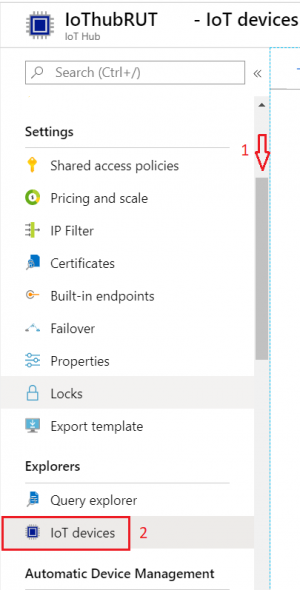
- Inside IoT Hub list:
Scroll down to Explorers and select IoT devices
- Press New
-
In new device creation1. Enter Device ID2. Leave everything else on default and press Save
- After creating a new device you will be redirected back to IoT devices. Select the newly created Device ID
- In the device window you will find information needed to connect Teltonika devices to Azure IoT Hub.
- Select Resource groups
If it is not in very first page, click More services and locate it there.


Configuring Azure IoT Hub on RutOS
To configure an Azure IoT Hub instance on the Teltonika device it is essential to install the Azure IoT Hub package via the package manager.
- To install required package navigate to System > Package Manager and install Azure IoT Hub package

Navigate to Services > Cloud solutions > Azure IoT Hub and add a new instance. In the pop-up window there will be two different connection types available:
- Shared Access signature (SAS) key
- Device Provisioning Service (DPS)
In this article both connection types will be demonstrated.
SAS key connection type configuration
Configuring Azure IoT Hub using the SAS key connection type is straightforward:

After the instance is correctly configured the connection status icon will be visible. A green dot indicates that the connection is successful.

Device Provisioning Service (DPS) configuration
The IoT Hub Device Provisioning Service (DPS) is a helper service for IoT Hub that enables zero-touch, just-in-time provisioning to the right IoT hub without requiring human intervention, allowing customers to provision millions of devices in a secure and scalable manner.
One of the primary features of DPS is its capability to dynamically manage multiple device identities. This service manages the device identity creation using enrollments which can be configured using the following attestation types:
- 1. X.509 intermediate certificates
- 2. Symmetric keys
To learn more about DPS service read about it here
DPS X.509 attestation
- Root CA certificate
- Intermediate CA certificate
- Devices certificates 2. After successfully generating the certificates return to the Azure portal page and navigate to your Azure IoT Hub Device Provisioning Service (DPS) page. From there proceed create an enrollment group. Refer to the Microsoft guide, section "Create an enrollment group" for in depth information.
- In the ID scope field specify your Azure DPS service ID. This value can be retrieved from the DPS instance found on Azure Portal page or by following the earlier guides from Microsoft.
- In the Registration ID field enter the "REG_ID" value that was specified in the earlier script.
- In the Symmetric key field enter the output value of the script that was used earlier].
The required certificates and keys:
3. Return to the device WebUI and navigate to Services -> Cloud Solutions -> Azure IoT Hub page to create a new configuration instance:
3.1 Set connection type as a Device Provisioning Service (DPS);
3.2 Enter ID Scope of your DPS service page on Azure. This value can be retrieved from the DPS instance found on Azure Portal page or by following the earlier guide;
3.3 Specify the Registration ID. This is the subject common name (CN) of the device leaf certificate that was created using the earlier guide.
3.4 Upload the certificate chain file and the private key file.
With all the required values in place the configuration pop-up window should resemble the screenshot below:

After a couple of moments the status of the configured instance status icon should turn green indicating the device has successfully established connection to Azure server.

DPS Symmetric key mechanism
The Symmetric key mechanism configuration is more straightforward. To configure it go back to the Azure portal page, navigate to your DPS service page and create a new enrollment group with the Symmetric key attestation mechanism.

Inspecting the newly created enrollment group will reveal some keys. The primary key will be used to derive each individual device identity. This can be done using a script which is available on Microsoft DPS documentation here.
The script contains a couple of variables: KEY and REG_ID. The KEY field shall contain the primary key which is obtained from the newly created enrollment group. The REG_ID field specifies the device identity name that will be created. Upon executing the script a shared access key will be created.

Go back to the device WebUI Services -> Cloud Solutions -> Azure IoT Hub configuration page and add a new instance. In the configuration window select DPS connection type and Symmetric Key connection type.
If you are following this guide your configuration window should look similar to the screenshot below.

After a few moments the device should establish connection to the Azure server.
After returning to the IoT Hub services in the Azure portal page it can be observed that the DPS service has created a new device identity was named the same as what we specified in the REG_ID field in the script.

Direct methods configuration
IoT Hub direct methods enable you to remotely invoke calls on devices from the cloud. Direct methods follow a request-response pattern and are meant for communications that require immediate confirmation of their result.
By default, all configuration instances will have this option disabled. To enable it, navigate on the router WebUI to Services -> Cloud Solutions -> Azure IoT Hub and press the edit button on the specific instance. Afterwards the "Enable Direct Methods" option needs to be enabled.

For testing and demonstration purposes we will use the Azure IoT Explorer application. The Azure IoT Explorer is a graphical tool for interacting with devices connected to your IoT hub. To learn more about this tool you can follow the Microsoft documentation here.
After enabling the Direct Method feature go to Azure IoT Explorer, select the appropriate device identity and navigate to the Direct Methods tab. All our devices support the api_call direct method which exposes the API interface to be used from the Azure side. In this example we will make a simple GET request to retrieve the I/O status of the device. Full documentation of Teltonika devices API can be found here .
The Azure IoT Explorer Direct Method tab will have a Payload field. In this field the api_call method expects JSON formatted data.

The API call expects at least two parameters. The first one is called "method" which needs to have an integer value between zero and three, corresponding to the API method type - either GET, POST, PUT or DELETE. The second parameter is "endpoint" which expects a string value of the API endpoint. In this case, we will call the /io/status endpoint.

After pressing the "Invoke Method" button the response from the device will be visible which is a standard API response specified in our documentation.

To determine the appropriate payload and method to use we provide an additional file currently called teltonikaGenericDevice.json. This file is written in Digital Twin Definition Language (DTDL). To learn more about DTDLs and Digital Twins read about it in Microsoft documentation here.
In this file you can see that it supports the api_call method, which accepts three values. The request body is optional, as some methods, such as the GET method, may not require it. JSON files can be downloaded here.
The IoT Explorer can be configured to parse DTDL files and display them to the user for easier work:
IoT plug and Play configuration
Navigate to the "IoT Plug and Play components" tab on the IoT Explorer. Initially there may be an error stating that it did not retrieve an interface model. To resolve this click on the "Configure" button. In this guide a local folder will be added by pressing the "Add" button.

The specified directory must have the DTDL ".json" files. After adding the local folder press the "Save" button.
Return to the device identity Plug and Play tab. Now you will be able to see two components with model IDs named "genericDevice" and "deviceInformation". The generic device will display the DTDL interface description.

In the upper toolbar select the "Commands" tab. There you will see that IoT Explorer has parsed the API call method and created three new fields. Now we can try to call the same I/O status method that we called previously.

We can see that some information was correctly retrieved from the router. This workflow makes it easier to work with API calls from the Azure side.
Sending data with "Data to Server" feature
The Data to Server service allows you to set up collections that collect data from various sources and periodically sends it to various servers. We can configure this feature to send data from the device to Azure IoT Hub.
Data to Server configuration
To configure the Data to Server service on Teltonika devices navigate to Services -> Data to Server on the WebUI. This guide will cover only the collection output part. To learn more about Data to Server features you can find the dedicated guide on our Wiki. From this point it is assumed the collection is properly set up with correct inputs.
In the "Configuration type" field you can choose whether to use an existing Azure IoT Hub configuration or configure a new and unique Azure IoT Hub configuration. In this example we will stick with the previously created Azure IoT Hub instance configuration. If you choose to create a new unique Azure IoT Hub configuration on the Data to Server instance you will need to input all the options that were discussed earlier in this guide.
If you are following this guide your configuration should resemble something similar to the screenshot below.

Checking if data reaches IoT Hub on Azure
To determine whether data successfully reaches Azure IoT Hub select your device and navigate to the "Telemetry" tab on the Azure IoT Explorer. Ensure that "Use built-in event hub" option is enabled and press the "Start" button. After some time you should see that data was sent from the device to the Azure IoT Hub.

Example use cases
This section shows some practical examples that combines most of the features that are discussed earlier.
Dynamically monitoring Modbus data
This example shows how to monitor and dynamically control Modbus data purely from the Azure cloud. We will set up a simple Modbus TCP server and client with Data to Server which will forward all the incoming Modbus data to Azure IoT Hub. In the end, using Direct Methods we will showcase how Modbus TCP client can collect and report different data from the cloud.

For this we will be using the following services:
- Azure IoT Hub;
- Data to Server;
- Modbus TCP Server;
- Modbus TCP Client;
- An Azure IoT Hub account.
In this example the Azure IoT Hub WebUI service configuration will not be covered since all the necessary information can be found in the earlier sections.
Modbus TCP Server
Enable the service in Services -> Modbus -> Modbus TCP Server with Enable option. For more information about this service you can find it on our Modbus Wiki TCP server section
Modbus TCP Client
Go to Services -> Modbus -> Modbus TCP Client page and create a new instance. This part will assume most of the configuration for this page is already made. For more information about this service you can find it on our Modbus Wiki TCP client section.
For this use case a single Modbus request configuration will be created to request the current device timestamp:
- Data type: 32bit UINT, Byte order 1,2,3,4
- Function: Read holding registers (3)
- First register number: 2
- Register counter/Values: 2
For device specific Modbus register information refer to the appropriate Wiki documentation.
Data to Server
1. Go to Services -> Data to Server page and create a new collection instance.
1.1. Select the input Type to Modbus;
1.2. Change the Format type to Custom;
1.3. In the Format string we will enter the following data: {"Date (Linux timestamp)": %timestamp%, "MODBUS server ID": "%server_id%", "MODBUS server name" : "%server_name%", "Request name": "%name%", "Start register": "%addr%", "Register data (JSON object)": %data%, "Raw data": "%raw_data%"}. This will form requests about Modbus data including the register values;
1.4. In the Collection configuration page select the Format type to custom;
1.5. Change the Format string to { "input1": %input1% }. Make sure to change the %input1% value to your specific input name. Note that this value is not enclosed in braces. This is intentional since the braces are present in the Modbus input Format string field;
1.6. In the Server configuration select the Type to Azure IoT Hub and configure the Azure configuration instance in accordance to your needs.
Monitoring and controlling incoming data
Inspecting the incoming data to the Azure IoT Hub using Azure IoT Explorer reveals that Modbus data is being received successfully.

In order to change the type of Modbus data sent to the Azure IoT Hub without going to the device WebUI the Direct Methods feature can be utilized. Using Azure IoT Explorer go to the device identity that was configured on the Teltonika device and select Direct method tab.
Using the api_call direct method create API requests that update the Modbus TCP Client request configurations (API reference for Modbus services can be found here. In this example the request configuration will be changed to collect Mobile signal strength. To do this using only API we will need to resolve the Modbus TCP client instance ID then the request ID of the instance which currently collects the temperature data. Using both of the IDs we will form the last API PUT request to update the register values:
2.1. Invoke /modbus/client/tcp/config GET request and inspect the output on IoT Explorer. The "data" array will contain JSON objects of every configured client instance. The "id" value will be used when forming the next API request;

2.2. Invoke /modbus/client/tcp/{id}/requests/config GET request and replace the {id} with the "id" value from the previous step. Inspecting the output will reveal the "data" array which contain JSON objects of every configured request. The "id" value of the request that collects temperature data will be used when forming the next API request;

2.3. Invoke /modbus/client/tcp/{id}/requests/config/{request_id} PUT request and replace the {id} with the "id" value from the 2.1. step and replace the {request_id} with the "id" value from the 2.2. step. In the request_body field add values to change the first register and data type values: {"data":{"first_reg":"4","data_type":"32bit_int1234"}} which corresponds to mobile signal strength register (other parameters such as number of registers stay the same since the timestamp register count is the same too).

2.4. Observe the incoming telemetry data. At this point the register data shall contain the mobile signal strength values.

This concludes the Azure IoT Hub guide. Using Direct Methods with device API is a powerful tool that unlocks new capabilities of device monitoring and control from the cloud. Nearly all features available via device WebUI are also available using API.
External links
- https://azure.microsoft.com/en-us/
- https://developers.teltonika-networks.com/
- https://learn.microsoft.com/en-us/azure/iot/howto-use-iot-explorer
- https://learn.microsoft.com/en-us/azure/iot-dps/how-to-legacy-device-symm-key?tabs=linux&%3Bpivots=programming-language-ansi-c&pivots=programming-language-ansi-c#derive-a-device-key
- https://learn.microsoft.com/en-us/azure/iot-dps/tutorial-custom-hsm-enrollment-group-x509?pivots=programming-language-ansi-c#create-a-root-ca-certificate

