Difference between revisions of "VLAN Set Up Test"
(Created page with "== Introduction == This article contains instructions o how to set up VLAN using a Teltonika-Networks device. Following this example, you will be able to create two different...") |
|||
| Line 1: | Line 1: | ||
| + | <p style="color:red">The information in this page is updated in accordance with firmware version '''[https://wiki.teltonika-networks.com/view/FW_%26_SDK_Downloads 00.07.09.01]'''. | ||
== Introduction == | == Introduction == | ||
This article contains instructions o how to set up VLAN using a Teltonika-Networks device. Following this example, you will be able to create two different networks (network interfaces) and limit speed on one of the interfaces (or both of them). | This article contains instructions o how to set up VLAN using a Teltonika-Networks device. Following this example, you will be able to create two different networks (network interfaces) and limit speed on one of the interfaces (or both of them). | ||
| − | For this example, I will be using the | + | For this example, I will be using the RUTX14 device. |
| + | If you're having trouble finding any page or some of the parameters described here on your device's WebUI, you should turn on '''"Advanced WebUI"''' mode. You can do that by clicking the '''"Advanced"''' button which is located at the top-right corner of the WebUI. | ||
| + | [[File:Networking rutos manual webui basic advanced mode 75.gif|border|class=tlt-border|1004x1004px]] | ||
== Creating VLAN == | == Creating VLAN == | ||
To create a VLAN follow all the steps below: | To create a VLAN follow all the steps below: | ||
| − | + | Access your device WebUI by typing your Routers Private or Public IP in your browser (my router has private IP 192.168.1.1) | |
| − | + | Next, navigate to '''Network → Vlan → Port Based''' | |
| − | * Now you'll need to add a new VLAN and change the first VLAN ('''ID:1''') configuration. | + | <table class="nd-othertables_2"> |
| − | + | <tr> | |
| − | [[File: | + | <th width=250; style="border-bottom: 1px solid white;></th> |
| + | <th width=950; style="border-bottom: 1px solid white"; rowspan=2>[[File:2024-09-25 09h34 42.png|800px|border|class=tlt-border|right]]</th> | ||
| + | </tr> | ||
| + | <tr> | ||
| + | <td style="border-bottom: 4px solid white> | ||
| + | * Now you'll need to add a new VLAN and change the first VLAN ('''ID:1''') configuration. | ||
| + | *# Press [[File:Add Button.png|60x90px]]. | ||
| + | *# Choose which port you will use and turn that port '''Off''' in VLAN ('''ID:1'''). In this example, lan3 port was chosen. | ||
| + | *# Turn on the selected LAN port in the new VLAN by selecting untagged from the dropdown meniu. | ||
| + | *# Press [[File:Save & Apply.png|100x30px]]. | ||
| + | </td> | ||
| + | </tr> | ||
| + | </table> | ||
| + | '''Note''' some of the devices when navigated to '''Network → Vlan → Port Based''' will not have any VLANs and only two will apear once [[File:Add Button.png|60x90px]] were pressed. In this situation your new VLAN will have ID '''2'''. | ||
| + | |||
| + | Before [[File:Add Button.png|60x90px]]: | ||
| + | [[File:Vlan before add button.png|1100px|border|class=tlt-border]] | ||
| + | ---- | ||
| + | After [[File:Add Button.png|60x90px]]: | ||
| + | [[File:2024-09-25 10h14 51.png|1100px|border|class=tlt-border]] | ||
| − | |||
==Creating Interface's== | ==Creating Interface's== | ||
| − | *Now navigate to '''Network → | + | *Now navigate to '''Network → LAN''' |
| − | *Add a new instance, by | + | *Add a new instance, by pressing [[File:Add Button.png|60x90px]]: |
| − | [[File: | ||
| − | * | + | * In General Settings: |
| − | |||
| − | |||
| − | |||
| − | |||
| − | |||
| − | [[File: | + | <table class="nd-othertables_2"> |
| + | <tr> | ||
| + | <th width=400; style="border-bottom: 1px solid white;></th> | ||
| + | <th width=600; style="border-bottom: 1px solid white"; rowspan=2>[[File:Newlaninterfaceconfig.png|border|class=tlt-border|right]]</th> | ||
| + | </tr> | ||
| + | <tr> | ||
| + | <td style="border-bottom: 4px solid white> | ||
| + | *# Enable the instance. | ||
| + | *# Write the '''desired name'''. | ||
| + | *# Write the '''desired IP address'''. | ||
| + | *# Select '''desired netmask''' from the dropdown meniu. | ||
| + | *# If needed enable '''DHCP'''. | ||
| + | </td> | ||
| + | </tr> | ||
| + | </table> | ||
| + | ---- | ||
| + | * In Physical Settings: | ||
| + | <table class="nd-othertables_2"> | ||
| + | <tr> | ||
| + | <th width=250; style="border-bottom: 1px solid white;></th> | ||
| + | <th width=950; style="border-bottom: 1px solid white"; rowspan=2>[[File:Newlanphysicalsettings.png|800px|border|class=tlt-border|right]]</th> | ||
| + | </tr> | ||
| + | <tr> | ||
| + | <td style="border-bottom: 4px solid white> | ||
| + | *# Frow the dropdown meniu select new VLAN interface. | ||
| + | *# Press [[File:Save & Apply.png|100x30px]]. | ||
| + | </td> | ||
| + | </tr> | ||
| + | </table> | ||
| − | * | + | *If you've configurated everything correctly your new Interface should be running: |
| − | |||
| − | [[File: | + | [[File:Newinterfacewithvlan.png|1000px|border|class=tlt-border]] |
| − | |||
| − | |||
| − | |||
| − | |||
| − | |||
==Testing new VLAN== | ==Testing new VLAN== | ||
| Line 46: | Line 83: | ||
Now by plugging my PC into the Ethernet cable with the RUTX11 LAN2 port you need to check if everything is working correctly. To do that you'll need: | Now by plugging my PC into the Ethernet cable with the RUTX11 LAN2 port you need to check if everything is working correctly. To do that you'll need: | ||
| + | <table class="nd-othertables_2"> | ||
| + | <tr> | ||
| + | <th width=250; style="border-bottom: 1px solid white;></th> | ||
| + | <th width=950; style="border-bottom: 1px solid white"; rowspan=2>[[File:Vlan6.png|center|thumb]]</th> | ||
| + | </tr> | ||
| + | <tr> | ||
| + | <td style="border-bottom: 4px solid white> | ||
*On your Windows machine open '''CMD''' (you can do it by typing in Windows search "'''CMD'''" and press '''Enter'''): | *On your Windows machine open '''CMD''' (you can do it by typing in Windows search "'''CMD'''" and press '''Enter'''): | ||
| − | + | </td> | |
| − | [[File: | + | </tr> |
| − | + | </table> | |
| + | ---- | ||
| + | <table class="nd-othertables_2"> | ||
| + | <tr> | ||
| + | <th width=250; style="border-bottom: 1px solid white;></th> | ||
| + | <th width=950; style="border-bottom: 1px solid white"; rowspan=2>[[File:Vlan7.png|center|thumb|499x499px]]</th> | ||
| + | </tr> | ||
| + | <tr> | ||
| + | <td style="border-bottom: 4px solid white> | ||
*In CMD type the command "'''ipconfig'''", press '''Enter''' and search for '''Ethernet adapter''' and check if you got the '''IP''' address like I did ('''192.168.2.x'''): | *In CMD type the command "'''ipconfig'''", press '''Enter''' and search for '''Ethernet adapter''' and check if you got the '''IP''' address like I did ('''192.168.2.x'''): | ||
| + | </td> | ||
| + | </tr> | ||
| + | </table> | ||
| − | |||
If you did, then you've done everything correctly, if you didn't go through all set up again and check if you have missed anything. | If you did, then you've done everything correctly, if you didn't go through all set up again and check if you have missed anything. | ||
| Line 64: | Line 118: | ||
Note: If you set '''QoS''' for the '''LAN''' interface, the direction logic is naturally inverted. Egress means "from router towards '''LAN'''" = in practice "download from '''WAN''' forwarded to '''LAN'''". | Note: If you set '''QoS''' for the '''LAN''' interface, the direction logic is naturally inverted. Egress means "from router towards '''LAN'''" = in practice "download from '''WAN''' forwarded to '''LAN'''". | ||
| − | For more detailed information about how to configure QoS and how it works, you can read it [https://wiki.teltonika-networks.com/view/ | + | For more detailed information about how to configure QoS and how it works, you can read it [https://wiki.teltonika-networks.com/view/RUTX14_Traffic_Shaping here]. |
[[Category:Networking]] | [[Category:Networking]] | ||
Revision as of 11:22, 25 September 2024
Main Page > FAQ > Networking > VLAN Set Up TestThe information in this page is updated in accordance with firmware version 00.07.09.01.
Introduction
This article contains instructions o how to set up VLAN using a Teltonika-Networks device. Following this example, you will be able to create two different networks (network interfaces) and limit speed on one of the interfaces (or both of them).
For this example, I will be using the RUTX14 device.
If you're having trouble finding any page or some of the parameters described here on your device's WebUI, you should turn on "Advanced WebUI" mode. You can do that by clicking the "Advanced" button which is located at the top-right corner of the WebUI.

Creating VLAN
To create a VLAN follow all the steps below:
Access your device WebUI by typing your Routers Private or Public IP in your browser (my router has private IP 192.168.1.1) Next, navigate to Network → Vlan → Port Based
Note some of the devices when navigated to Network → Vlan → Port Based will not have any VLANs and only two will apear once ![]() were pressed. In this situation your new VLAN will have ID 2.
were pressed. In this situation your new VLAN will have ID 2.
Creating Interface's
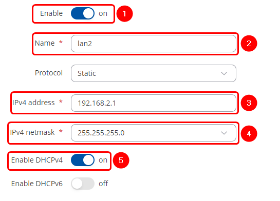
- In General Settings:
|
- In Physical Settings:
- If you've configurated everything correctly your new Interface should be running:
Testing new VLAN
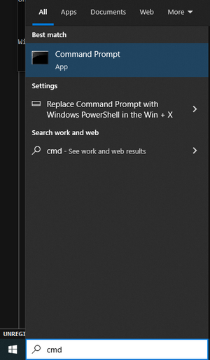
Now by plugging my PC into the Ethernet cable with the RUTX11 LAN2 port you need to check if everything is working correctly. To do that you'll need:
|
|
If you did, then you've done everything correctly, if you didn't go through all set up again and check if you have missed anything.
Setting up data limit on the interface
This step is optional, complete this if you need to limit internet data on one of your interfaces (or both).
You'll need to create a QoS configuration, for this you'll need to download the QoS package in Services → Package Manager → Packages and limit the internet speed for an interface that you want to be limited.
Note: If you set QoS for the LAN interface, the direction logic is naturally inverted. Egress means "from router towards LAN" = in practice "download from WAN forwarded to LAN".
For more detailed information about how to configure QoS and how it works, you can read it here.


