VXLAN Configuration Example: Difference between revisions
No edit summary |
|||
| (81 intermediate revisions by the same user not shown) | |||
| Line 1: | Line 1: | ||
''VXLAN support has been introduced starting with firmware version 00.07.09 and later. It is advised to update to the latest firmware available. | ''VXLAN support has been introduced starting with firmware version 00.07.09 and later. It is advised to update to the latest firmware available. | ||
'' | '' | ||
<p style="color:red">The information in this page is updated in accordance with | <p style="color:red">The information in this page is updated in accordance with '''00.07.10''' firmware version.</p> | ||
==Introduction== | ==Introduction== | ||
| Line 17: | Line 17: | ||
Navigate to '''System > Package Manager''' | Navigate to '''System > Package Manager''' | ||
#In the search bar look for | #In the search bar look for '''VXLAN''' package | ||
#Click '''Install''' | #Click '''Install''' | ||
[[File:Vxlan package manager installation.png|border|class=tlt-border]] | [[File:Vxlan package manager installation.png|border|class=tlt-border]] | ||
==VXLAN over Wired WAN== | ==VXLAN over Wired WAN== | ||
[[File:Vxlan wired wan topology.png|border|class=tlt-border|1100px]] | |||
In this section, the setup of VXLAN over Wired WAN using RUT1 and RUT2 devices will be described. The process will show how to create a VXLAN tunnel to connect the devices and allow them to communicate over the wired network. | In this section, the setup of VXLAN over Wired WAN using RUT1 and RUT2 devices will be described. The process will show how to create a VXLAN tunnel to connect the devices and allow them to communicate over the wired network. | ||
===Configuration on RUT1 device=== | ===Configuration on RUT1 device=== | ||
---- | ---- | ||
Navigate to the '''Network > WAN''' section in the WebUI, then click the | Navigate to the '''Network > WAN''' section in the WebUI, then click the [[File:Edit button.png]] button for the wired WAN interface. | ||
[[File:Vxlan_over_wan_config_rut1_wan_p1.png|border|class=tlt-border]] | [[File:Vxlan_over_wan_config_rut1_wan_p1.png|border|class=tlt-border]] | ||
| Line 41: | Line 42: | ||
[[File:Vxlan over wired vxlan settings add.png|border|class=tlt-border]] | [[File:Vxlan over wired vxlan settings add.png|border|class=tlt-border]] | ||
#<li value="3">Enter name of the new VXLAN interface | #<li value="3">Enter name of the new VXLAN interface | ||
# Enter the Remote address corresponding to RUT2 wired WAN interface IP address | #Enter VNI (VXLAN Network Identifier). It identifies a specific virtual network in a data plane and performs a function similar to a VLAN ID in regular networks. The same VNI have to be used in RUT2 VXLAN interface settings. | ||
#Enter the port number. The default port is 4789 | |||
#Enter the Remote address corresponding to RUT2 wired WAN interface IP address | |||
# Click [[File:Save & Apply.png|90px]] twice | # Click [[File:Save & Apply.png|90px]] twice | ||
[[File:Vxlan over wired vxlan settings | [[File:Vxlan over wired vxlan rut1 settings.png|border|class=tlt-border]] | ||
Navigate to '''Network > LAN''' and click | Navigate to '''Network > LAN''' and click [[File:Edit button.png]] to modify existing LAN interface | ||
[[File:Vxlan over wired lan config.png|border|class=tlt-border]] | [[File:Vxlan over wired lan config.png|border|class=tlt-border]] | ||
In '''Physical Settings''' tab: | |||
#Asure that '''Bridge interfaces''' option is enabled | #Asure that '''Bridge interfaces''' option is enabled | ||
#Click on the droplist and add vxlan1 interface | #Click on the droplist and add '''vxlan1''' interface | ||
#Click [[File:Save & Apply.png|90px]] twice | #Click [[File:Save & Apply.png|90px]] twice | ||
| Line 58: | Line 62: | ||
---- | ---- | ||
The configuration steps for RUT2 are similar to those performed on RUT1, with some additional adjustments. Navigate to the '''Network > WAN''' section in the WebUI, then click the | The configuration steps for RUT2 are similar to those performed on RUT1, with some additional adjustments. Navigate to the '''Network > WAN''' section in the WebUI, then click the [[File:Edit button.png]] button for the wired WAN interface. | ||
[[File:Vxlan_over_wan_config_rut1_wan_p1.png|border|class=tlt-border]] | [[File:Vxlan_over_wan_config_rut1_wan_p1.png|border|class=tlt-border]] | ||
| Line 73: | Line 77: | ||
#Press [[File:Add Button.png|50px]] | #Press [[File:Add Button.png|50px]] | ||
[[File:Vxlan over wired vxlan settings add.png|border|class=tlt-border]] | [[File:Vxlan over wired vxlan settings add.png|border|class=tlt-border]] | ||
#<li value="3">Enter name of the new VXLAN interface | #<li value="3">Enter name of the new VXLAN interface | ||
#Enter the Remote address corresponding to | #Enter VNI (VXLAN Network Identifier). It identifies a specific virtual network in a data plane and performs a function similar to a VLAN ID in regular networks. The same VNI have to be used in RUT2 VXLAN interface settings. | ||
#Enter the same port number that is configured in the RUT1 VXLAN settings | |||
#Enter the Remote address corresponding to RUT2 wired WAN interface IP address | |||
#Click [[File:Save & Apply.png|90px]] twice | #Click [[File:Save & Apply.png|90px]] twice | ||
[[File:Vxlan over wired vxlan settings | [[File:Vxlan over wired vxlan rut2 settings.jpg|border|class=tlt-border]] | ||
Navigate to '''Network > LAN''' and click | Navigate to '''Network > LAN''' and click [[File:Edit button.png]] to modify existing LAN interface. | ||
[[File:Vxlan over wired lan config rut2.png|border|class=tlt-border]] | [[File:Vxlan over wired lan config rut2.png|border|class=tlt-border]] | ||
#For testing purposes, both routers should be part of the same LAN segment, so assign unique IP addresses to prevent conflicts. | #For testing purposes, both routers should be part of the same LAN segment, so assign unique IP addresses to prevent conflicts. RUT2 will now be accessible using its newly assigned IP address. | ||
#Additionally, only one DHCP server | #Additionally, ensure that only one DHCP server is active by disabling the DHCP server on RUT2. | ||
[[File:Vxlan over wired lan settings RUT2.png|border|class=tlt-border]] | [[File:Vxlan over wired lan settings RUT2.png|border|class=tlt-border]] | ||
#<li value="3">Asure that Bridge interfaces option is enabled | |||
In '''Physical Settings''' tab: | |||
#<li value="3">Asure that '''Bridge interfaces''' option is enabled | |||
#Click on the droplist and add vxlan1 interface | #Click on the droplist and add vxlan1 interface | ||
#Click [[File:Save & Apply.png|90px]] twice | #Click [[File:Save & Apply.png|90px]] twice | ||
[[File:Vxlan over wired lan physical settings RUT2.png|border|class=tlt-border]] | [[File:Vxlan over wired lan physical settings RUT2.png|border|class=tlt-border]] | ||
===Configuration | ==VXLAN over Mobile network== | ||
[[File:Vxlan mobile wan topology.png|border|class=tlt-border|1100px]] | |||
In this section, VXLAN will be set up between two Teltonika devices using Mobile WAN, requiring two public IPs—one for each RUT device. The configuration steps will be similar to those described in the [[#VXLAN over Wired WAN|VXLAN over Wired WAN]] section of this page, except for the '''APN''' settings and the '''Network > Devices''' section settings, where the remote address of the created VXLAN interface will be updated to reflect the other router's public IP. | |||
===Configuring APN settings=== | |||
---- | |||
First, both RUT1 and RUT2 devices must have '''Public IP''' addresses. To achieve this, manually assign the relevant APN settings to their mobile interfaces to obtain Public IPs: | |||
Navigate to the '''Network > WAN''' section in the WebUI, then click the [[File:Edit button.png]] button for the mobile WAN interface. | |||
[[File:Vxlan over mobile wan config rut1 rev2.png|border|class=tlt-border]] | |||
:Configuration window will open. Adjust the following: | |||
#Disable '''Auto APN''' | |||
#Select an APN that will provide your router with a '''Public IP''' | |||
# Click [[File:Save & Apply.png|90px]] twice | |||
[[File:Vxlan over mobile wan config rut1 2.png|border|class=tlt-border]] | |||
===Configuration on RUT1 device=== | |||
---- | ---- | ||
Configuration | Navigate to '''Network > Devices'''. To create a new instance, click the [[File:Add Button.png|50px]] button. If editing an existing interface from the [[#VXLAN over Wired WAN|'''previous configuration''']], click [[File:Edit button.png]] | ||
#In '''Remote address''' section enter '''RUT2 Public IP''' address | |||
# Click [[File:Save & Apply.png|90px]] twice | |||
[[File:Vxlan over mobile vxlan settings.png|border|class=tlt-border]] | |||
===Configuration on RUT2 device=== | |||
---- | |||
Navigate to '''Network > Devices'''. To create a new instance, click the [[File:Add Button.png|50px]] button. If editing an existing interface from the [[#VXLAN over Wired WAN|'''previous configuration''']], click [[File:Edit button.png]] | |||
#In '''Remote address''' section enter '''RUT1 Public IP''' address | |||
# Click [[File:Save & Apply.png|90px]] twice | |||
[[File:Vxlan | [[File:Vxlan over mobile vxlan settings.png|border|class=tlt-border]] | ||
==VXLAN over VPN tunnel== | |||
[[File:Vxlan vpn topology.png|border|class=tlt-border|1100px]] | |||
[[File:Vxlan | If only one Public IP address is available, VXLAN can be configured through a VPN tunnel. In this case, an IPsec VPN will be used, where RUT1 acts as the VPN server and RUT2 as the client. The VPN creates remote tunnel endpoints, which can then be integrated into the VXLAN configuration to enable Layer 2 communication between the routers. | ||
The configuration steps will be similar to those outlined in the [[#VXLAN over Wired WAN|VXLAN over Wired WAN]] section of this page, with the addition of '''IPsec configuration''' and adjustments in the '''Network > Devices''' settings, where the remote address of the created VXLAN interface will be updated to correspond to the VPN tunnel endpoint of the other router. | |||
===Configuration on RUT1 device=== | ===Configuration on RUT1 device=== | ||
---- | ---- | ||
Navigate to the ''' | Navigate to '''Services > VPN > IPsec''': | ||
[[File:Vxlan over | #Enter Instance name | ||
#Click on the [[File:Add Button.png|50px]] | |||
[[File:Vxlan over vpn add server.png|border|class=tlt-border]] | |||
#<li value="3"> Enable instance | |||
#Since RUT1 will serve as the server device, the Remote endpoint field should be left blank | |||
#Select '''Pre-Shared Key''' as the authentication method | |||
#Enter the key. This key must match the one that will be entered later in the RUT2 IPSec settings | |||
#Enter the RUT1 LAN IP address as the '''Local identifier''' | |||
#Enter the RUT2 LAN IP address as the '''Remote identifier''' | |||
[[File:Vxlan over vpn server settings p1.png|border|class=tlt-border]] | |||
:Scroll down to '''Connection settings''': | |||
#<li value="9">Select "'''Start'''" in '''Mode''' section | |||
#Select "'''Tunnel'''" as connection type | |||
#Enable "'''Route based IPSec'''" | |||
#Enter the '''IP address''' of the RUT1 tunnel endpoint | |||
#Enter lower MTU to reduce packet size (optional) | |||
#<li value="14">Leave all other settings at their default values and click the [[File:Save & Apply.png|90px]] twice | |||
[[File:Vxlan over vpn server settings p2.png|border|class=tlt-border]] | |||
Navigate to '''Network > Devices'''. To create a new instance, click the [[File:Add Button.png|50px]] button. If editing an existing interface from the [[#VXLAN over Wired WAN|'''previous configuration''']], click [[File:Edit button.png]] | |||
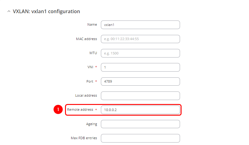
#Enter '''IP address''' of RUT2 VPN '''tunnel endpoint''' | |||
#Click the [[File:Save & Apply.png|90px]] twice | |||
[[File:Vxlan over vpn vxlan settings rut1.png|border|class=tlt-border]] | |||
===Configuration on RUT2 device=== | |||
---- | |||
Navigate to '''Services > VPN > IPsec''': | |||
#Enter Instance name | |||
#Click on the [[File:Add Button.png|50px]] | |||
[[File:Vxlan over vpn add client.png|border|class=tlt-border]] | |||
#<li value="3"> Enable instance | |||
#Enter RUT1 Public IP | |||
#Select '''Pre-Shared Key''' as the authentication method | |||
#Enter the key. This key must match the one that was entered the RUT1 IPSec settings | |||
#Enter the RUT2 LAN IP address as the '''Local identifier''' | |||
#Enter the RUT1 LAN IP address as the '''Remote identifier''' | |||
[[File:Vxlan over vpn client settings p1 rev1.png|border|class=tlt-border]] | |||
:Scroll down to '''Connection settings''': | |||
#<li value="9">Select "'''Start'''" in '''Mode''' section | |||
#Select "'''Tunnel'''" as connection type | |||
#Enable "'''Route based IPSec'''" | |||
#Enter the '''IP address''' of the RUT2 tunnel endpoint | |||
#Enter lower MTU to reduce packet size (optional) | |||
#Leave all other settings at their default values and click the [[File:Save & Apply.png|90px]] twice | |||
[[File:Vxlan over vpn client settings p2.png|border|class=tlt-border]] | |||
Navigate to '''Network > Devices'''. To create a new instance, click the [[File:Add Button.png|50px]] button. If editing an existing interface from the [[#VXLAN over Wired WAN|'''previous configuration''']], click [[File:Edit button.png]] | |||
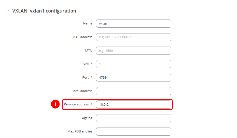
#Enter '''IP address''' of RUT1 VPN '''tunnel endpoint''' | |||
#Click the [[File:Save & Apply.png|90px]] twice | |||
[[File:Vxlan over vpn vxlan settings rut2.png|border|class=tlt-border]] | |||
[[File:Vxlan over | |||
==Configuration testing== | |||
The best way to test the configuration after setting up VXLAN between the routers is to ping between devices on either side of the routers using their LAN IPs and check the ARP tables. This ensures that devices on the same LAN segment can communicate over the Layer 2 (L2) network through the routers. | |||
Configuration testing from RUT1 side: | |||
[[File:Vxlan | [[File:Vxlan ping rut1 to rut2.png|border|class=tlt-border]] | ||
If the MAC address for the specified IP address in the ARP table matches the RUT2's MAC address, it confirms that the configuration is functioning correctly. | |||
[[File:Vxlan arp rut1.png|border|class=tlt-border]] | |||
[[File:Vxlan | Configuration testing from RUT2 side: | ||
[[File:Vxlan ping rut2 to rut1.png|border|class=tlt-border]] | |||
[[File:Vxlan arp rut2.png|border|class=tlt-border]] | |||
Latest revision as of 07:57, 28 October 2024
VXLAN support has been introduced starting with firmware version 00.07.09 and later. It is advised to update to the latest firmware available.
The information in this page is updated in accordance with 00.07.10 firmware version.
Introduction
VXLAN (Virtual Extensible LAN) encapsulates Layer 2 Ethernet frames within Layer 3 packets, creating a Layer 2 network over a Layer 3 infrastructure. It acts as a virtual switch, interconnecting routers and all devices connected to them into an extended Layer 2 network, enhancing scalability and flexibility. In this article several methods to configure a VXLAN tunnel between two Teltonika devices will be demonstrated.
Prerequisites
- Two routers with installed VXLAN packages, will refer to these as RUT1 and RUT2
- End device like Laptop or Mobile Phone
- Two Public IP addresses for configuring VXLAN over the Mobile network
- One Public IP address for configuring VXLAN over the VPN tunnel
VXLAN package Installation
First, install the VXLAN package on both RUT1 and RUT2 devices. This package is available on firmware version 07.09 and later, therefore, updating the router's firmware is a mandatory step if it is outdated. After the update, the package can be found in the Package Manager in the WebUI.
Navigate to System > Package Manager
- In the search bar look for VXLAN package
- Click Install
VXLAN over Wired WAN
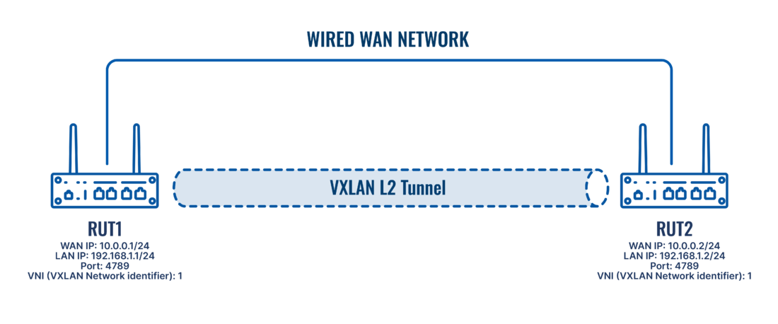 In this section, the setup of VXLAN over Wired WAN using RUT1 and RUT2 devices will be described. The process will show how to create a VXLAN tunnel to connect the devices and allow them to communicate over the wired network.
Configuration on RUT1 device
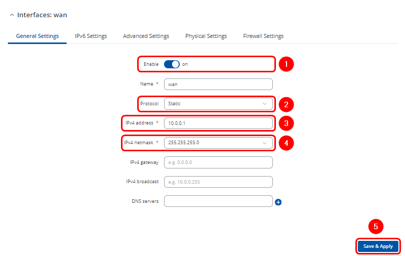
Navigate to the Network > WAN section in the WebUI, then click the ![]() button for the wired WAN interface.
button for the wired WAN interface.

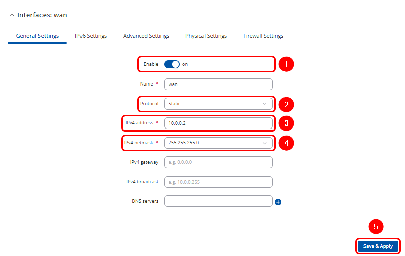
- Configuration window will open. Adjust following:
- Ensure interface is Enabled
- Change Protocol to Static
- Enter Ipv4 address for communication in this Wired WAN network
- Select your preferable IPv4 netmask
- Click
 twice
twice
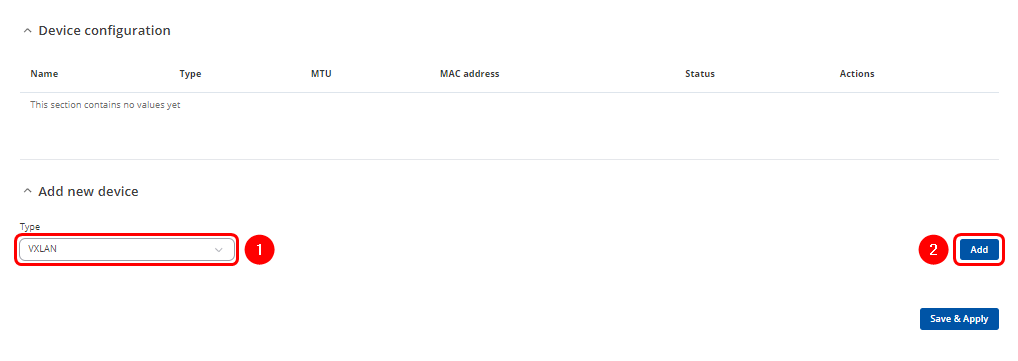
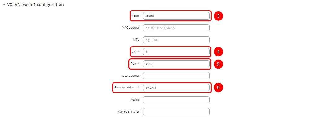
Navigate to the Network > Devices
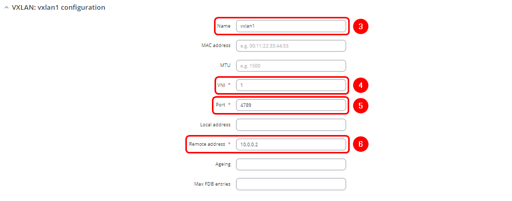
- Enter name of the new VXLAN interface
- Enter VNI (VXLAN Network Identifier). It identifies a specific virtual network in a data plane and performs a function similar to a VLAN ID in regular networks. The same VNI have to be used in RUT2 VXLAN interface settings.
- Enter the port number. The default port is 4789
- Enter the Remote address corresponding to RUT2 wired WAN interface IP address
- Click
 twice
twice
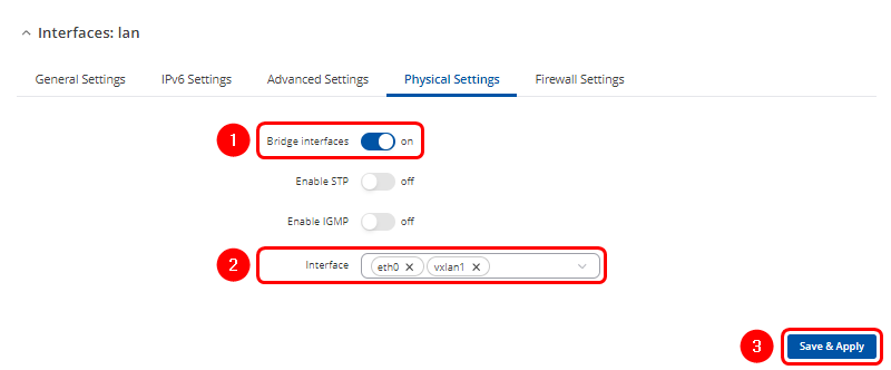
Navigate to Network > LAN and click ![]() to modify existing LAN interface
to modify existing LAN interface
In Physical Settings tab:
- Asure that Bridge interfaces option is enabled
- Click on the droplist and add vxlan1 interface
- Click
 twice
twice
Configuration on RUT2 device
The configuration steps for RUT2 are similar to those performed on RUT1, with some additional adjustments. Navigate to the Network > WAN section in the WebUI, then click the ![]() button for the wired WAN interface.
button for the wired WAN interface.

Configuration window will open. Adjust following:
- Ensure interface is Enabled
- Change Protocol to Static
- Enter Ipv4 address for communication in this Wired WAN network
- Select your preferable IPv4 netmask
- Click
 twice
twice
Navigate to the Network > Devices
- Enter name of the new VXLAN interface
- Enter VNI (VXLAN Network Identifier). It identifies a specific virtual network in a data plane and performs a function similar to a VLAN ID in regular networks. The same VNI have to be used in RUT2 VXLAN interface settings.
- Enter the same port number that is configured in the RUT1 VXLAN settings
- Enter the Remote address corresponding to RUT2 wired WAN interface IP address
- Click
 twice
twice
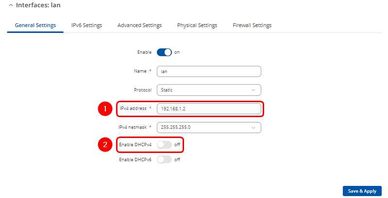
Navigate to Network > LAN and click ![]() to modify existing LAN interface.
to modify existing LAN interface.

- For testing purposes, both routers should be part of the same LAN segment, so assign unique IP addresses to prevent conflicts. RUT2 will now be accessible using its newly assigned IP address.
- Additionally, ensure that only one DHCP server is active by disabling the DHCP server on RUT2.
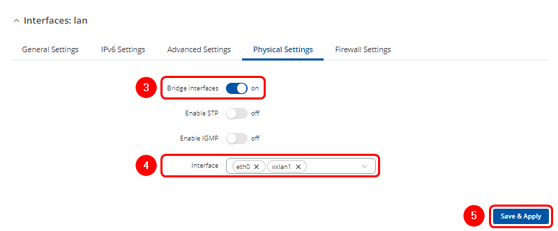
In Physical Settings tab:
- Asure that Bridge interfaces option is enabled
- Click on the droplist and add vxlan1 interface
- Click
 twice
twice
VXLAN over Mobile network
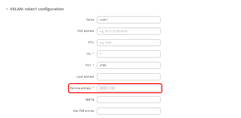
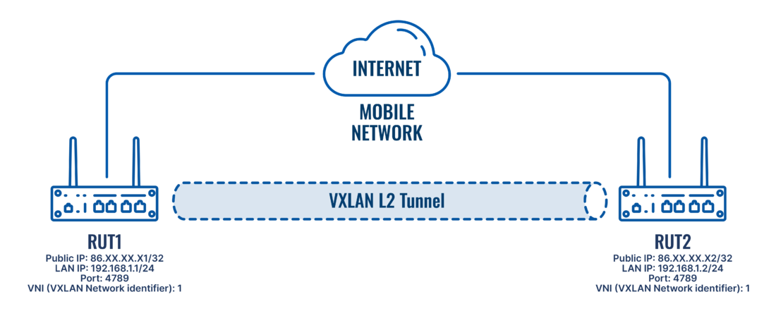 In this section, VXLAN will be set up between two Teltonika devices using Mobile WAN, requiring two public IPs—one for each RUT device. The configuration steps will be similar to those described in the VXLAN over Wired WAN section of this page, except for the APN settings and the Network > Devices section settings, where the remote address of the created VXLAN interface will be updated to reflect the other router's public IP.
Configuring APN settings
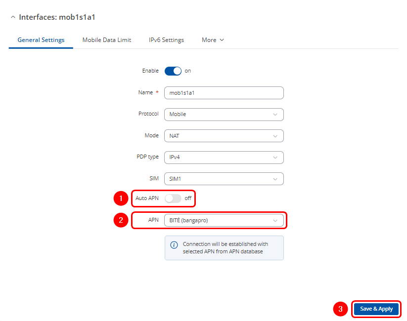
First, both RUT1 and RUT2 devices must have Public IP addresses. To achieve this, manually assign the relevant APN settings to their mobile interfaces to obtain Public IPs:
Navigate to the Network > WAN section in the WebUI, then click the ![]() button for the mobile WAN interface.
button for the mobile WAN interface.

- Configuration window will open. Adjust the following:
Configuration on RUT1 device
Navigate to Network > Devices. To create a new instance, click the ![]() button. If editing an existing interface from the previous configuration, click
button. If editing an existing interface from the previous configuration, click ![]()
Configuration on RUT2 device
Navigate to Network > Devices. To create a new instance, click the ![]() button. If editing an existing interface from the previous configuration, click
button. If editing an existing interface from the previous configuration, click ![]()
VXLAN over VPN tunnel
 If only one Public IP address is available, VXLAN can be configured through a VPN tunnel. In this case, an IPsec VPN will be used, where RUT1 acts as the VPN server and RUT2 as the client. The VPN creates remote tunnel endpoints, which can then be integrated into the VXLAN configuration to enable Layer 2 communication between the routers.
The configuration steps will be similar to those outlined in the VXLAN over Wired WAN section of this page, with the addition of IPsec configuration and adjustments in the Network > Devices settings, where the remote address of the created VXLAN interface will be updated to correspond to the VPN tunnel endpoint of the other router.
Configuration on RUT1 device
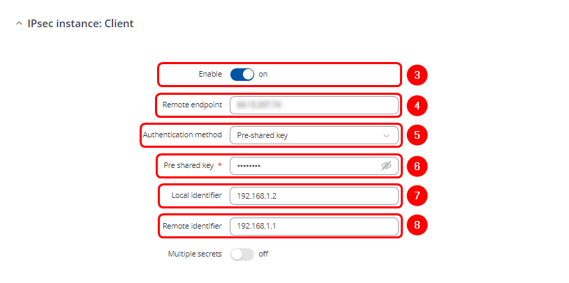
Navigate to Services > VPN > IPsec:
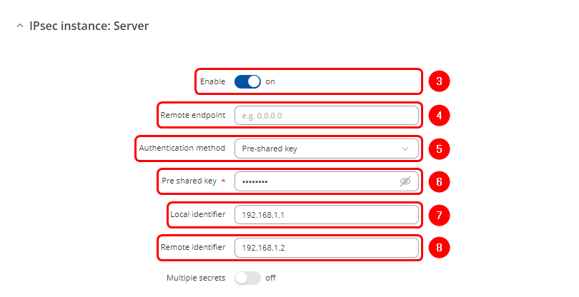
- Enable instance
- Since RUT1 will serve as the server device, the Remote endpoint field should be left blank
- Select Pre-Shared Key as the authentication method
- Enter the key. This key must match the one that will be entered later in the RUT2 IPSec settings
- Enter the RUT1 LAN IP address as the Local identifier
- Enter the RUT2 LAN IP address as the Remote identifier
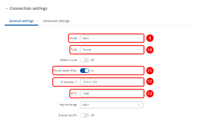
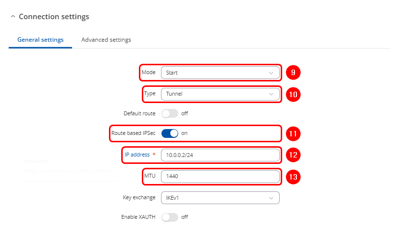
- Scroll down to Connection settings:
- Select "Start" in Mode section
- Select "Tunnel" as connection type
- Enable "Route based IPSec"
- Enter the IP address of the RUT1 tunnel endpoint
- Enter lower MTU to reduce packet size (optional)
- Leave all other settings at their default values and click the
 twice
twice
Navigate to Network > Devices. To create a new instance, click the ![]() button. If editing an existing interface from the previous configuration, click
button. If editing an existing interface from the previous configuration, click ![]()
Configuration on RUT2 device
Navigate to Services > VPN > IPsec:
- Enable instance
- Enter RUT1 Public IP
- Select Pre-Shared Key as the authentication method
- Enter the key. This key must match the one that was entered the RUT1 IPSec settings
- Enter the RUT2 LAN IP address as the Local identifier
- Enter the RUT1 LAN IP address as the Remote identifier
- Scroll down to Connection settings:
- Select "Start" in Mode section
- Select "Tunnel" as connection type
- Enable "Route based IPSec"
- Enter the IP address of the RUT2 tunnel endpoint
- Enter lower MTU to reduce packet size (optional)
- Leave all other settings at their default values and click the
 twice
twice
Navigate to Network > Devices. To create a new instance, click the ![]() button. If editing an existing interface from the previous configuration, click
button. If editing an existing interface from the previous configuration, click ![]()
Configuration testing
The best way to test the configuration after setting up VXLAN between the routers is to ping between devices on either side of the routers using their LAN IPs and check the ARP tables. This ensures that devices on the same LAN segment can communicate over the Layer 2 (L2) network through the routers.
Configuration testing from RUT1 side:
If the MAC address for the specified IP address in the ARP table matches the RUT2's MAC address, it confirms that the configuration is functioning correctly.


