OpenRemote: Difference between revisions
No edit summary |
|||
| (5 intermediate revisions by 2 users not shown) | |||
| Line 1: | Line 1: | ||
[[File:Networking_rutos_configuration_examples_openremote_logo.png|right]] | |||
=Introduction= | =Introduction= | ||
| Line 8: | Line 9: | ||
You will need: | You will need: | ||
* OpenRemote system | * OpenRemote system; | ||
* A router from | * A router from RUT or TRB series; | ||
=Hardware Description= | =Hardware Description= | ||
| Line 70: | Line 71: | ||
*For Bluetooth, first you have to pair the device you want to get data from | *For Bluetooth, first you have to pair the device you want to get data from | ||
*For WiFi scanner data, you have to enable the wifi scanner functionality first | *For WiFi scanner data, you have to enable the wifi scanner functionality first | ||
*For MODBUS data, you need to set what data from what MODBUS | *For MODBUS data, you need to set what data from what MODBUS Server the router has to get | ||
If you need any help on setting up each functionality, the Teltonika Wiki has topics for each one of them: [[RUTX11 Bluetooth|Bluetooth]], [[RUTX11 Wireless|WiFi Scanner]], [[RUTX11 Modbus|MODBUS]] | If you need any help on setting up each functionality, the Teltonika Wiki has topics for each one of them: [[RUTX11 Bluetooth|Bluetooth]], [[RUTX11 Wireless|WiFi Scanner]], [[RUTX11 Modbus|MODBUS]] | ||
===First example: Publishing RUT MODBUS to OpenRemote manager using MQTT=== | ===First example: Publishing RUT MODBUS to OpenRemote manager using MQTT=== | ||
[[File: | [[File:Networking_rutos_configuration_examples_openremote_020_v2.png|border|center|class=tlt-border]] | ||
In this example the RUT device will act as MODBUS TCP | In this example the RUT device will act as MODBUS TCP Client and MODBUS TCP Server, so the device will make requests (Client) and answer to himself (Server). The received reply, will be sent over MQTT. You can also send data from another MODBUS Server devices connected to the router. | ||
====Enabling MODBUS TCP | ====Enabling MODBUS TCP Server==== | ||
Enabling the MODBUS | Enabling the MODBUS Server option on the router allows it to answer any requests coming from a MODBUS Client. To do that, go to the router configuration page→Services→MODBUS→MODBUS TCP Server. Then clock the "Enable" slider and save. | ||
[[File: | [[File:Networking_rutos_config_example_openremote_1.png|border|class=tlt-border]] | ||
====Enabling MODBUS TCP | ====Enabling MODBUS TCP Client==== | ||
Enabling the MODBUS | Enabling the MODBUS Client option on the router allows it to make specific requests to any Server in the MODBUS network. To do that, go to the router configuration page '''Services → MODBUS → MODBUS TCP Client'''. Click on the '''"Add"''' button, and do the following configuration on the page: | ||
#'''Enable''' the instance | |||
#'''"Name"''' : Any name | |||
#'''"Server ID"''' : The Server ID you've set on the Server configuration, by default its 1 | |||
#'''"IP address"''' : The LAN IP address of the router, by default its 192.168.1.1 | |||
#'''"Port"''' : 502 | |||
Other settings can be configured by your needs. | |||
[[File:Networking_rutos_config_example_openremote_2.png|border|class=tlt-border]] | |||
Then scroll down the page a bit, on the "Add new request" section, give any name to your request and click on the "Add" button. Then do the following configuration: | |||
'''" | #Enter your desired '''name'''. | ||
#Click on the '''Add''' button. | |||
# '''"Data type"''' : Data type of the data you are going to receive, in this case, the router reports its device system uptime | |||
# '''"Function"''' : MODBUS Protocol function, in this case, we are going to Read holding registers | |||
# '''"First register number"''' : Depends on your MODBUS device, in this case, its 2 | |||
# '''"Register count / Values"''' : Depends on your MODBUS device, in this case, its 2 | |||
# '''Enable''' the configuration. | |||
[[File:Networking_rutos_config_example_openremote_3.png|border|class=tlt-border|1000px]] | |||
[[File: | |||
Save and apply settings. | Save and apply settings. | ||
| Line 118: | Line 116: | ||
Go to the router configuration page→Services→[https://wiki.teltonika-networks.com/view/Data_to_Server Data to server]. Click on the "Add" button, and the configuration is basically the same as described on the "Publishing Bluetooth/Wifi scanner/Modbus data" section of this article, just change the data source to "MODBUS data" and format the data as you wish. You should have something similar to this. | Go to the router configuration page→Services→[https://wiki.teltonika-networks.com/view/Data_to_Server Data to server]. Click on the "Add" button, and the configuration is basically the same as described on the "Publishing Bluetooth/Wifi scanner/Modbus data" section of this article, just change the data source to "MODBUS data" and format the data as you wish. You should have something similar to this. | ||
'''" | *'''"Name"''' : Any name | ||
'''" | *'''"Type"''' : Modbus data | ||
[[File:Networking_rutos_config_example_openremote_4.png|border|class=tlt-border]] | |||
''' | *'''In collection configuration''' you can leave everything by default and move onto '''Server configuration'''. | ||
Server configuration should be similiar: | |||
''' | #Choose Type '''MQTT''' | ||
#Choose the '''Server''' address where the data should be sent. | |||
#Write the '''Topic'''. Define the correct topic. For directly writing an attribute value: {realm}/{clientID}/writeattributevalue/{attributeName}/{assetID}. | |||
#Write the '''Client ID''' - should be the same that is used in topic | |||
#Enable '''Use credentials''' | |||
#Write the '''Username''' | |||
#Write the '''Password''' that was generated | |||
[[File:Networking_rutos_config_example_openremote_5.png|border|class=tlt-border]] | |||
====Checking if it works==== | ====Checking if it works==== | ||
Then, you can open the "OpenRemote" system to check if your setup works, if everything was setup correctly, you should see the values update in attributes section. In the example we could see that the data " | Then, you can open the "OpenRemote" system to check if your setup works, if everything was setup correctly, you should see the values update in attributes section. In the example we could see that the data "Server name - %N and registry data (JSON object) - %a" is being updated. | ||
[[File:Networking_rutos_configuration_examples_openremote_014.png|border|class=tlt-border]] | [[File:Networking_rutos_configuration_examples_openremote_014.png|border|class=tlt-border]] | ||
=References to OpenRemote= | =References to OpenRemote= | ||
| Line 204: | Line 149: | ||
# https://github.com/openremote/openremote/wiki | # https://github.com/openremote/openremote/wiki | ||
# Forum https://forum.openremote.io/ | # Forum https://forum.openremote.io/ | ||
[[Category:Third party services]] | |||
Latest revision as of 13:55, 5 November 2024
Main Page > General Information > Configuration Examples > Third party services > OpenRemote
Introduction
OpenRemote an intuitive user-friendly 100% open source IoT platform. You can build a complete IoT device management solution including: device management and auto provisioning, customisation of asset types, automation via when-then, flow, javascript and groovy rules, data analytics, connectivity via several protocol agents and manager APIs (e.g. MQTT broker, HTTP/REST, WS), Multi-tenancy (realms), Users and roles management, Edge gateway, Front-end UI web components and consoles, and an Insights dashboard builder.
In this article you will find instructions on how to setup OpenRemote Manager as a MQTT Broker and how to send telemetry data using Teltonika device to the OpenRemote platform.
Prerequisites
You will need:
- OpenRemote system;
- A router from RUT or TRB series;
Hardware Description
Hardware descriptions can be found in different Quick Start Guides (QSG). There you will find an overview of the various components on the front and back of a device, hardware installation instructions, first login information, device specifications, and general safety information. Link: Quick Start Guides
Set up your Development Environment
Teltonika Networks devices comes with our created firmware, therefore no additional development or scripting is required for this unit to support OpenRemote.
Setting up OpenRemote manager
Refer to the online OpenRemote documentation at Quckstart. Follow the steps in the section Quickstart to create your own environment with full access.
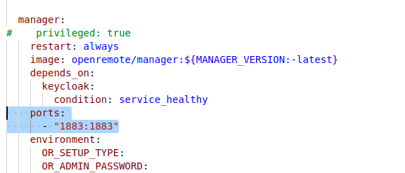
NOTE: In examples, port 1883 was used for MQTT protocol. To use this port you need to add it to your docker-compose file.
OpenRemote as MQTT broker and subscriber
Create a service user
The service user will give programmatic access to the MQTT client.
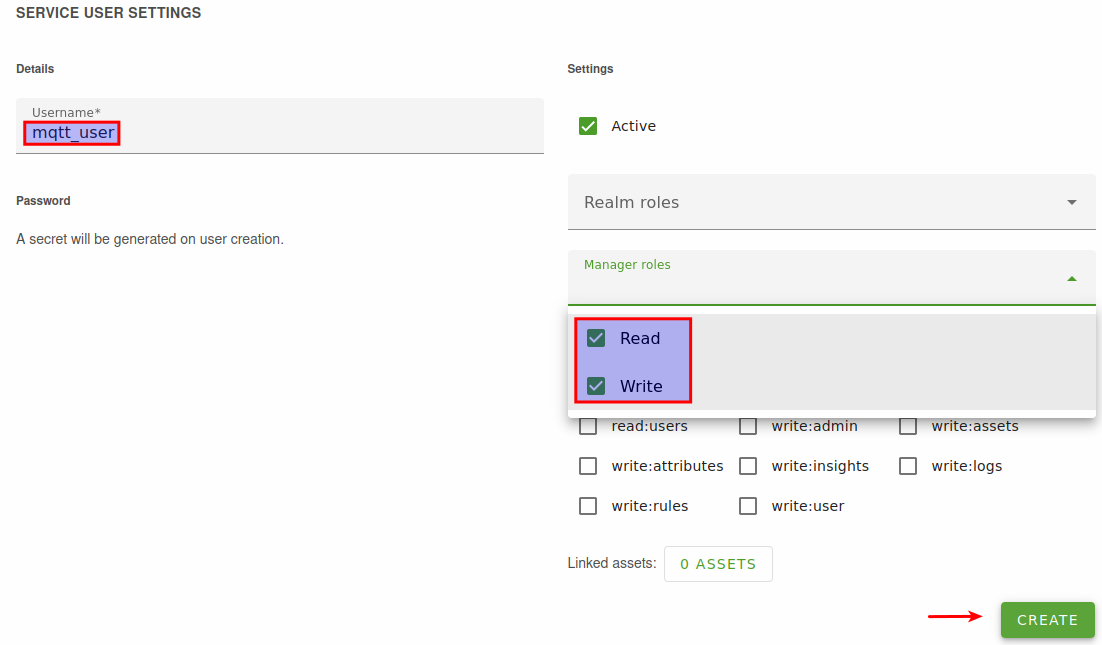
- Go to the users page and create a new service user (second panel on the page).
- Name the service user 'mqtt_user' and give the user the read and write role for the sake of convenience. It is advised to configure a more restricted role for your service users.
- Click 'Create', a secret will be generated automatically.
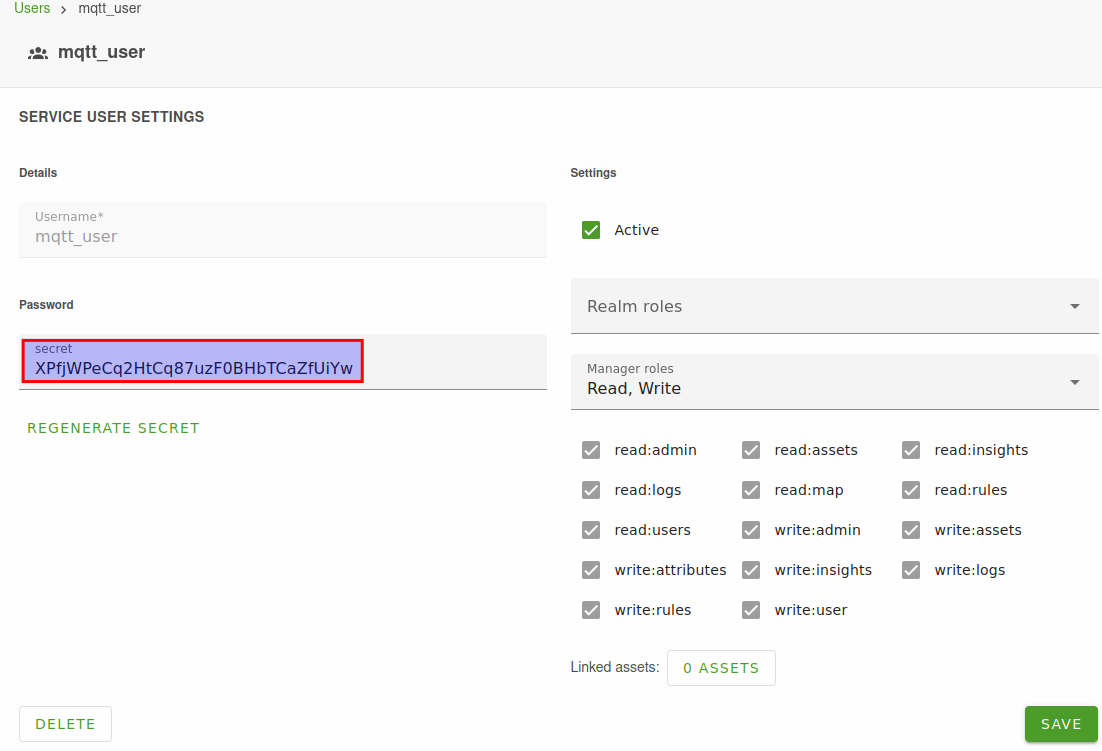
- Open the 'mqtt_user' user to see and copy the secret.
Create an asset with attributes
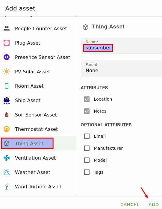
We will create a Thing asset (MQTT subscriber), but feel free to use an AssetType that matches your physical device.
- On the assets page, click the + in the asset tree on the left.
- Select the Thing asset type, give it a friendly name and click 'Add'.
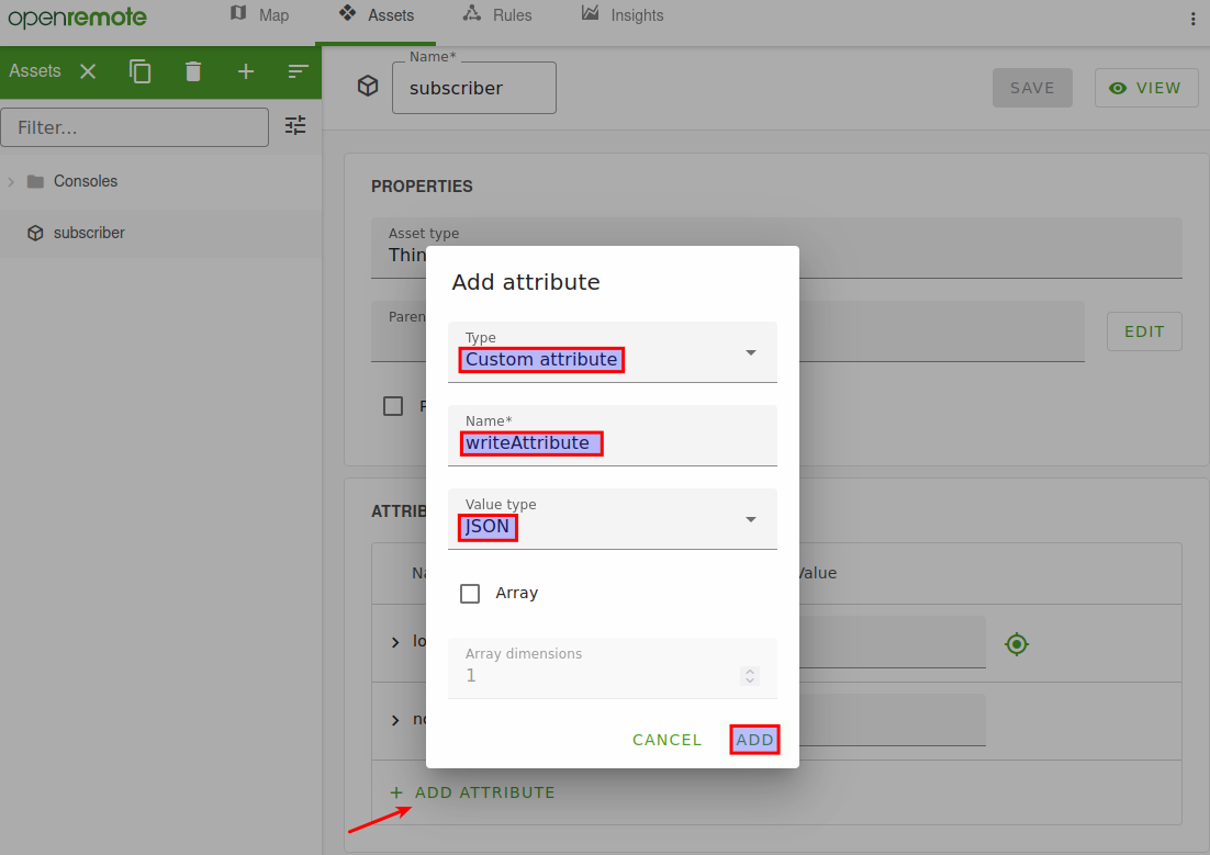
- Add new attribute in the Edit asset mode and save configuration:
- type: Custom Attribute
- name: writeAttribute
- Valuetype: JSON
RUT as MQTT Publisher
What data do you want to publish?
Depending on your RUT model, you can have the following options of data sources to send over MQTT:
- Bluetooth
- Wifi scanner
- MODBUS
Publishing Bluetooth/Wifi scanner/Modbus data
Before sending data from those sources to the MQTT Broker, the router needs to know what data from each source to send:
- For Bluetooth, first you have to pair the device you want to get data from
- For WiFi scanner data, you have to enable the wifi scanner functionality first
- For MODBUS data, you need to set what data from what MODBUS Server the router has to get
If you need any help on setting up each functionality, the Teltonika Wiki has topics for each one of them: Bluetooth, WiFi Scanner, MODBUS
First example: Publishing RUT MODBUS to OpenRemote manager using MQTT
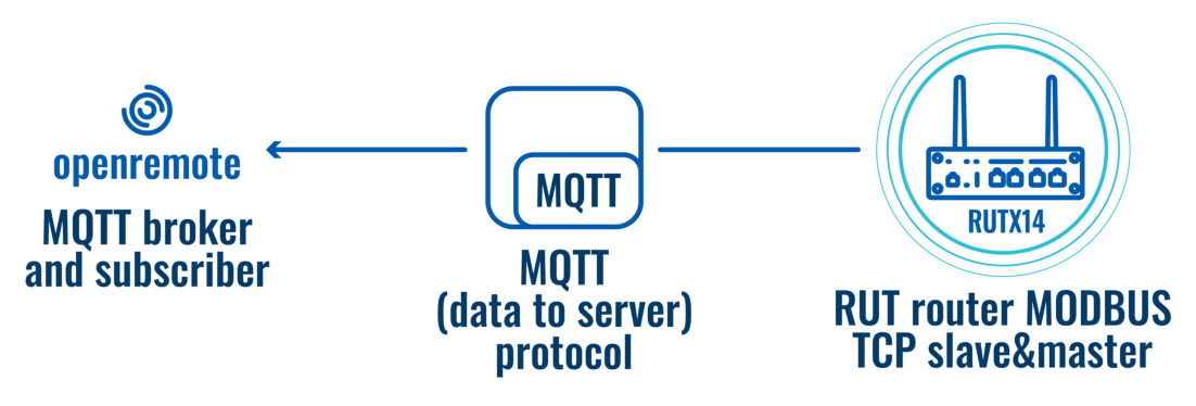
In this example the RUT device will act as MODBUS TCP Client and MODBUS TCP Server, so the device will make requests (Client) and answer to himself (Server). The received reply, will be sent over MQTT. You can also send data from another MODBUS Server devices connected to the router.
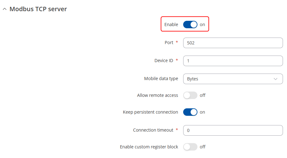
Enabling MODBUS TCP Server
Enabling the MODBUS Server option on the router allows it to answer any requests coming from a MODBUS Client. To do that, go to the router configuration page→Services→MODBUS→MODBUS TCP Server. Then clock the "Enable" slider and save.
Enabling MODBUS TCP Client
Enabling the MODBUS Client option on the router allows it to make specific requests to any Server in the MODBUS network. To do that, go to the router configuration page Services → MODBUS → MODBUS TCP Client. Click on the "Add" button, and do the following configuration on the page:
- Enable the instance
- "Name" : Any name
- "Server ID" : The Server ID you've set on the Server configuration, by default its 1
- "IP address" : The LAN IP address of the router, by default its 192.168.1.1
- "Port" : 502
Other settings can be configured by your needs.
Then scroll down the page a bit, on the "Add new request" section, give any name to your request and click on the "Add" button. Then do the following configuration:
- Enter your desired name.
- Click on the Add button.
- "Data type" : Data type of the data you are going to receive, in this case, the router reports its device system uptime
- "Function" : MODBUS Protocol function, in this case, we are going to Read holding registers
- "First register number" : Depends on your MODBUS device, in this case, its 2
- "Register count / Values" : Depends on your MODBUS device, in this case, its 2
- Enable the configuration.
Save and apply settings.
Configuring Data to Server
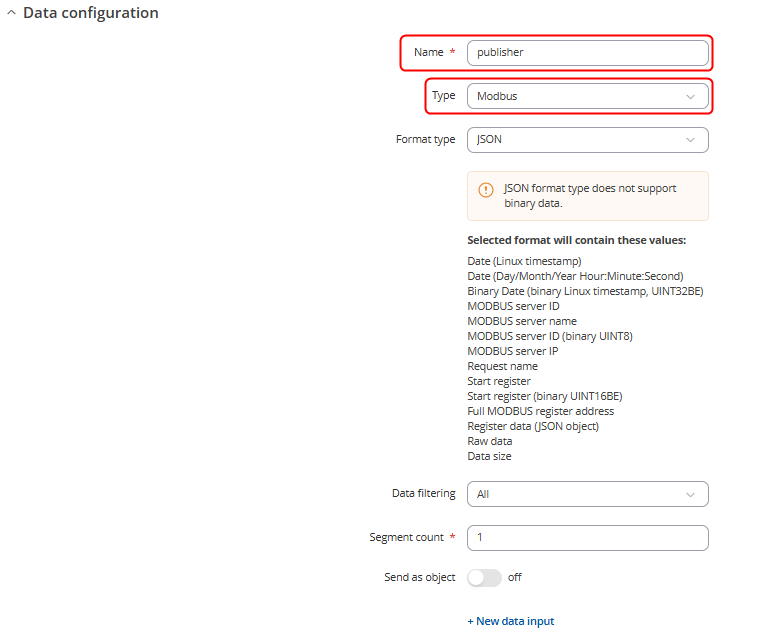
Go to the router configuration page→Services→Data to server. Click on the "Add" button, and the configuration is basically the same as described on the "Publishing Bluetooth/Wifi scanner/Modbus data" section of this article, just change the data source to "MODBUS data" and format the data as you wish. You should have something similar to this.
- "Name" : Any name
- "Type" : Modbus data
- In collection configuration you can leave everything by default and move onto Server configuration.
Server configuration should be similiar:
- Choose Type MQTT
- Choose the Server address where the data should be sent.
- Write the Topic. Define the correct topic. For directly writing an attribute value: {realm}/{clientID}/writeattributevalue/{attributeName}/{assetID}.
- Write the Client ID - should be the same that is used in topic
- Enable Use credentials
- Write the Username
- Write the Password that was generated
Checking if it works
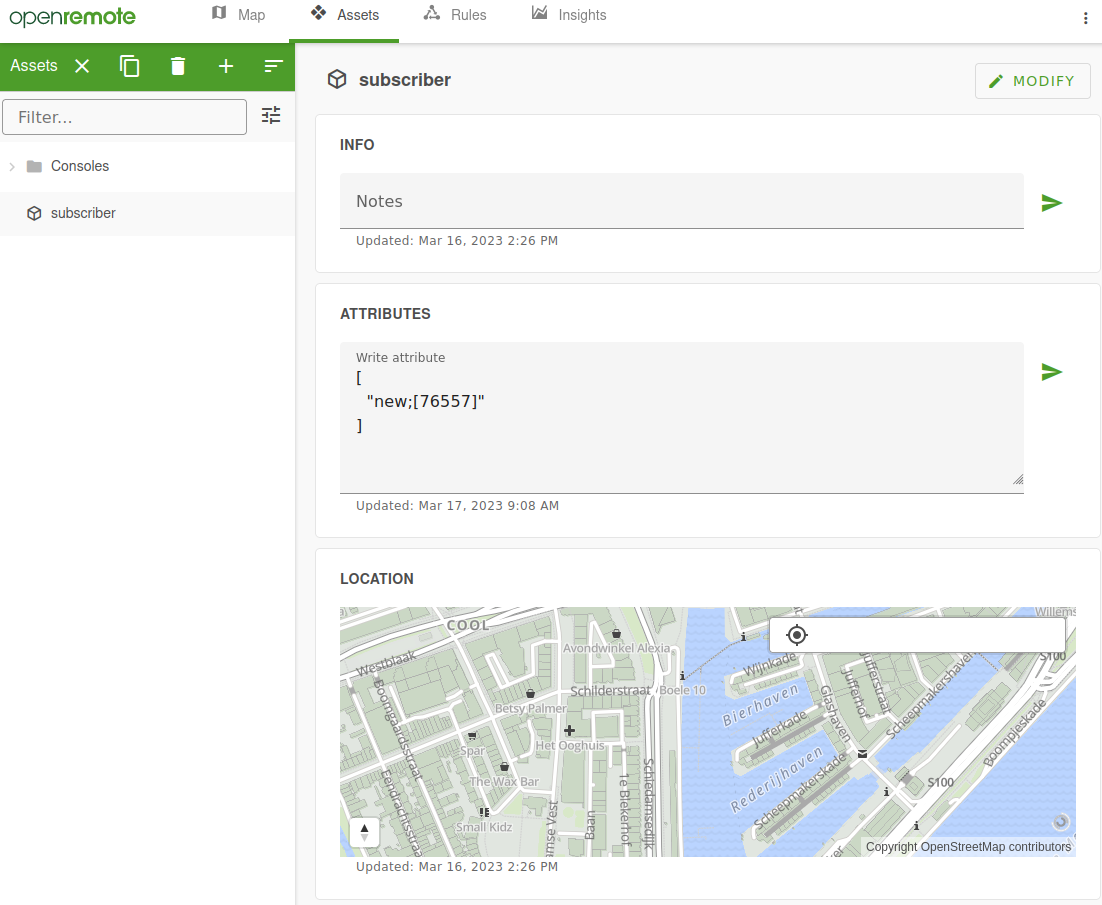
Then, you can open the "OpenRemote" system to check if your setup works, if everything was setup correctly, you should see the values update in attributes section. In the example we could see that the data "Server name - %N and registry data (JSON object) - %a" is being updated.


