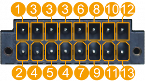
Template:Networking trb2xx manual 16 pin terminal block pinout: Difference between revisions
(Created page with "<table class="nd-othertables"> <tr> <th style="width: 352px" colspan="3">16 Pin Terminal Block Pinout</th> <th style="width: 250px; border-bottom: 1px soli...") |
No edit summary |
||
| (3 intermediate revisions by the same user not shown) | |||
| Line 2: | Line 2: | ||
<tr> | <tr> | ||
<th style="width: 352px" colspan="3">16 Pin Terminal Block Pinout</th> | <th style="width: 352px" colspan="3">16 Pin Terminal Block Pinout</th> | ||
<th style="width: 350px; border-bottom: 1px solid white;" colspan="1" rowspan="5"> | |||
</tr> | </tr> | ||
<tr> | <tr> | ||
<td style="width: 50px;">No.</td> | <td style="width: 50px;">No.</td> | ||
<td style="width: | <td style="width: 200px;"><b>Description</b></td> | ||
<td><b>Wire color</b></td> | <td><b>Wire color</b></td> | ||
</tr> | </tr> | ||
| Line 21: | Line 21: | ||
<tr> | <tr> | ||
<td style="font-weight: normal;">3</td> | <td style="font-weight: normal;">3</td> | ||
<td>Configurable | <td>Configurable Digital I/O pin</td> | ||
<td>-</td> | <td>-</td> | ||
</tr> | </tr> | ||
| Line 28: | Line 28: | ||
<td>Ground pin</td> | <td>Ground pin</td> | ||
<td>-</td> | <td>-</td> | ||
<th style="width: 400px; border-bottom: 1px solid white;" colspan="1" rowspan="10"> [[File:Networking_trb2x5_manual_trb2x5_16_pin_terminal_block_v1.png|300px|right|bottom]]</th> | |||
</tr> | </tr> | ||
<tr> | <tr> | ||

