Template:Networking device manual powering options passive poe table: Difference between revisions
(Created page with "{| class="wikitable" style="text-align: left;" |+<b>RJ45 pinout</b>: | style="width: 20px;" | <b>Pin</b> | style="width: 75px;" | <b>Signal ID</b> | style="width: 150px;" |...") |
No edit summary |
||
| (5 intermediate revisions by 2 users not shown) | |||
| Line 2: | Line 2: | ||
|+<b>RJ45 pinout</b>: | |+<b>RJ45 pinout</b>: | ||
| style="width: 20px;" | <b>Pin</b> | | style="width: 20px;" | <b>Pin</b> | ||
| | | colspan="2" | <b>10/100 mode B, DC on spares</b> | ||
| style="width: 150px;" | <b>T568A Color</b> | | style="width: 150px;" | <b>T568A Color</b> | ||
| style="width: 150px;" | <b>T568B Color</b> | | style="width: 150px;" | <b>T568B Color</b> | ||
| Line 8: | Line 8: | ||
|- | |- | ||
| 1 | | 1 | ||
| TX+ | | style="width: 50px;" | | ||
| style="width: 50px;" | TX+ | |||
| [[File:Poe white green stripe.png|75px]]<br>white/green stripe | | [[File:Poe white green stripe.png|75px]]<br>white/green stripe | ||
| [[File:Poe white orange stripe.png|75px]]<br>white/orange stripe | | [[File:Poe white orange stripe.png|75px]]<br>white/orange stripe | ||
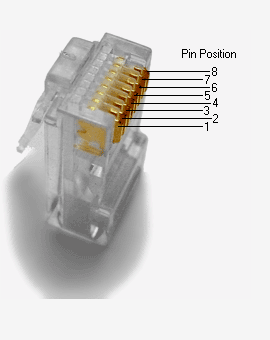
| rowspan="8" style="background: #F5F4F5;" | [[File:Poe rj45 connector.png| | | rowspan="8" style="background: #F5F4F5;" | [[File:Poe rj45 connector.png|400px]] | ||
|- | |- | ||
| 2 | | 2 | ||
| | |||
| TX- | | TX- | ||
| [[File:Poe solid green.png|75px]]<br>green solid | | [[File:Poe solid green.png|75px]]<br>green solid | ||
| Line 19: | Line 21: | ||
|- | |- | ||
| 3 | | 3 | ||
| | |||
| RX+ | | RX+ | ||
| [[File:Poe white orange stripe.png|75px]]<br>white/orange stripe | | [[File:Poe white orange stripe.png|75px]]<br>white/orange stripe | ||
| Line 24: | Line 27: | ||
|- | |- | ||
| 4 | | 4 | ||
| | | DC+ | ||
| 9-30 VDC | |||
| [[File:Poe solid blue.png|75px]]<br>blue solid | | [[File:Poe solid blue.png|75px]]<br>blue solid | ||
| [[File:Poe solid blue.png|75px]]<br>blue solid | | [[File:Poe solid blue.png|75px]]<br>blue solid | ||
|- | |- | ||
| 5 | | 5 | ||
| | |DC+ | ||
| 9-30 VDC | |||
| [[File:Poe white blue stripe.png|75px]]<br>white/blue stripe | | [[File:Poe white blue stripe.png|75px]]<br>white/blue stripe | ||
| [[File:Poe white blue stripe.png|75px]]<br>white/blue stripe | | [[File:Poe white blue stripe.png|75px]]<br>white/blue stripe | ||
|- | |- | ||
| 6 | | 6 | ||
| | |||
| RX- | | RX- | ||
| [[File:Poe solid orange.png|75px]]<br>orange solid | | [[File:Poe solid orange.png|75px]]<br>orange solid | ||
| Line 39: | Line 45: | ||
|- | |- | ||
| 7 | | 7 | ||
| | |DC- | ||
| | |||
| [[File:Poe white brown stripe.png|75px]]<br>white/brown stripe | | [[File:Poe white brown stripe.png|75px]]<br>white/brown stripe | ||
| [[File:Poe white brown stripe.png|75px]]<br>white/brown stripe | | [[File:Poe white brown stripe.png|75px]]<br>white/brown stripe | ||
|- | |- | ||
| 8 | | 8 | ||
| | |DC- | ||
| | |||
| [[File:Poe solid brown.png|75px]]<br>brown solid | | [[File:Poe solid brown.png|75px]]<br>brown solid | ||
| [[File:Poe solid brown.png|75px]]<br>brown solid | | [[File:Poe solid brown.png|75px]]<br>brown solid | ||
|- | |- | ||
|} | |} | ||

