Template:Networking rut955 manual modbus serial: Difference between revisions
No edit summary |
m Protected "Template:Networking rut955 manual modbus serial" ([Edit=Allow only administrators] (indefinite) [Move=Allow only administrators] (indefinite)) |
||
| (28 intermediate revisions by the same user not shown) | |||
| Line 1: | Line 1: | ||
== | ==Summary== | ||
'''Modbus''' is a serial communications protocol originally published by Modicon (now Schneider Electric) in 1979 for use with its programmable logic controllers (PLCs). Modbus has become a de facto standard communication protocol and is now a commonly available means of connecting industrial electronic devices. The main reasons for the use of Modbus in the industrial environment are: | '''Modbus''' is a serial communications protocol originally published by Modicon (now Schneider Electric) in 1979 for use with its programmable logic controllers (PLCs). Modbus has become a de facto standard communication protocol and is now a commonly available means of connecting industrial electronic devices. The main reasons for the use of Modbus in the industrial environment are: | ||
*developed with industrial applications in mind | *developed with industrial applications in mind; | ||
*openly published and royalty-free | *openly published and royalty-free; | ||
*easy to deploy and maintain | *easy to deploy and maintain; | ||
*moves raw bits or words without placing many restrictions on vendors. | *moves raw bits or words without placing many restrictions on vendors. | ||
Modbus enables communication among many devices connected to the same network, for example, a system that measures temperature and humidity and communicates the results to a computer. Modbus is often used to connect a supervisory computer with a remote terminal unit (RTU) in supervisory control and data acquisition (SCADA) systems. Many of the data types are named from its use in driving relays: a single-bit physical output is called a coil, and a single-bit physical input is called a discrete input or a contact. | Modbus enables communication among many devices connected to the same network, for example, a system that measures temperature and humidity and communicates the results to a computer. Modbus is often used to connect a supervisory computer with a remote terminal unit (RTU) in supervisory control and data acquisition (SCADA) systems. Many of the data types are named from its use in driving relays: a single-bit physical output is called a coil, and a single-bit physical input is called a discrete input or a contact. | ||
This article provides | This article provides a brief example on how to use Modbus serial to monitor a slave device, send data to server and how to configure slave alarms. To find more information about this feature visit [[RUT955 Modbus]] and [[RUT955 RS232/RS485]] pages. | ||
==Prerequisites== | ==Prerequisites== | ||
| Line 18: | Line 18: | ||
*Hercules and modRSsim applications | *Hercules and modRSsim applications | ||
*RS232 to USB cable | *RS232 to USB cable | ||
==Topology== | |||
[[File:Networking_rut955_configuration_modbus_serial_topology_2_v1.png|border|class=tlt-border|700x700px]] | |||
==Configuring Modbus serial slave device== | ==Configuring Modbus serial slave device== | ||
| Line 25: | Line 29: | ||
When you are done with that, open the app and apply the following configuration. | When you are done with that, open the app and apply the following configuration. | ||
[[File:|border|class=tlt-border]] | [[File:Networking_rut955_configuration_modbus_serial_1_v1.png|border|class=tlt-border]] | ||
# Select '''Protocol''' (MODBUS RS-232). | # Select '''Protocol''' (MODBUS RS-232). | ||
# Click '''Setup the communication Serial or TCP/IP port'''. | # Click '''Setup the communication Serial or TCP/IP port'''. | ||
[[File:|border|class=tlt-border]] | [[File:Networking_rut955_configuration_modbus_serial_2_v1.png|border|class=tlt-border]] | ||
# Select the '''Port''' which you connected RS232 cable to (to find which port you are using go to Windows search bar and write '''Device Manager''' then select '''Ports''' and see which one you are using). | # Select the '''Port''' which you connected RS232 cable to (to find which port you are using go to Windows search bar and write '''Device Manager''' then select '''Ports''' and see which one you are using). | ||
| Line 40: | Line 44: | ||
Open router’s WebUI, navigate to '''Services > Modbus > Modbus Serial Master''' and apply the following configuration. | Open router’s WebUI, navigate to '''Services > Modbus > Modbus Serial Master''' and apply the following configuration. | ||
[[File:|border|class=tlt-border]] | [[File:Networking_rut955_configuration_modbus_serial_3_v1.png|border|class=tlt-border]] | ||
# Press '''Enable'''. | # Press '''Enable'''. | ||
| Line 49: | Line 53: | ||
Now create '''RS232 slave''' by writing a name, pressing '''Add''' button. It should appear like in the example and then press '''Edit'''. | Now create '''RS232 slave''' by writing a name, pressing '''Add''' button. It should appear like in the example and then press '''Edit'''. | ||
[[File:|border|class=tlt-border]] | [[File:Networking_rut955_configuration_modbus_serial_4_v1.png|border|class=tlt-border]] | ||
Then apply the following configuration. | Then apply the following configuration. | ||
[[File:|border|class=tlt-border]] | [[File:Networking_rut955_configuration_modbus_serial_5_v1.png|border|class=tlt-border]] | ||
# Check '''Enable'''. | # Check '''Enable'''. | ||
| Line 62: | Line 66: | ||
Go back to the '''Slave configuration''' window and create '''Slave request''' by writing a name, pressing '''Add''' button. It should appear like in the example and then press '''Edit'''. | Go back to the '''Slave configuration''' window and create '''Slave request''' by writing a name, pressing '''Add''' button. It should appear like in the example and then press '''Edit'''. | ||
[[File:|border|class=tlt-border]] | [[File:Networking_rut955_configuration_modbus_serial_6_v1.png|border|class=tlt-border]] | ||
Then apply the following configuration. | Then apply the following configuration. | ||
[[File:|border|class=tlt-border]] | [[File:Networking_rut955_configuration_modbus_serial_7_v1.png|border|class=tlt-border]] | ||
# Check '''Enable'''. | # Check '''Enable'''. | ||
| Line 74: | Line 78: | ||
# Press '''Save'''. | # Press '''Save'''. | ||
==Modbus data server== | ==Modbus data to server== | ||
===Creating server=== | |||
---- | |||
In order to test the functionality, you will need to set up a server (you can run a server on the same computer you use as a slave simulator). | |||
There are many ways how you can create a server to which Modbus will send data to. In this example we are going to be using Windows 10 computer and Hercules app, which you can download [https://www.hw-group.com/product-version/hercules here], to create a test server. Download, install the app and apply the configuration below: | |||
[[File:Networking_rut955_configuration_modbus_serial_8_v1.png|border|class=tlt-border]] | |||
# Select '''TCP Server''' tab. | |||
# Enter '''Port''' (In this example default 1883 is used). | |||
# Click '''Listen''' | |||
And that is it, now you will be able to see the data coming from Modbus in the Received data section. | |||
===RUT Modbus data to server configuration=== | |||
---- | |||
In order to setup your router to send Modbus data to server you will need to navigate to '''Services > Modbus > Modbus Data to Server'''. | |||
[[File:Networking_rut955_configuration_modbus_serial_9_v1.png|border|class=tlt-border]] | |||
# Select '''Protocol''' (In this example HTTP(S) will be used). | |||
# Enter '''IP''' and '''port''' of the PC with the Hercules software. | |||
# Enter '''Period''' (minutes, how often router should send data to server). | |||
# Click '''ADD'''. | |||
Then you will be redirected to '''Advanced sender settings'''. | |||
[[File:Networking_rut955_configuration_modbus_serial_10_v1.png|border|class=tlt-border]] | |||
# Enter '''Name''' (It can be anything you want). | |||
# Click '''Save'''. | |||
===Receiving data=== | |||
---- | |||
Open Hercules again, press '''Listen''' and you should start receiving Modbus Data messages. | |||
[[File:Networking_rut955_configuration_modbus_serial_11_v1.png|border|class=tlt-border]] | |||
Try to change some data in the Modbus Slave simulator. | |||
[[File:Networking_rut955_configuration_modbus_serial_12_v1.png|border|class=tlt-border]] | |||
Received data should change. | |||
[[File:Networking_rut955_configuration_modbus_serial_13_v1.png|border|class=tlt-border]] | |||
==Slave alarms== | |||
In order to setup the following configuration SIM card is required. | |||
Go back to '''Services > Modbus > Modbus Serial Master''' and press edit the same Slave configuration or create a new one. There will be section called '''Slave alarms'''. Create a name, then press '''Add''' button. When it appears like in the example, press '''Edit'''. | |||
[[File:Networking_rut955_configuration_modbus_serial_14_v1.png|border|class=tlt-border]] | |||
Then apply the following configuration: | |||
[[File:Networking_rut955_configuration_modbus_serial_15_v1.png|border|class=tlt-border]] | |||
# '''Enable''' instance. | |||
# Select '''Function''' (Read Holding Registers). | |||
# Write '''Register''' (1). | |||
# Select '''Condition''' (More than). | |||
# Write '''Value''' (5). | |||
# Select '''Action''' (SMS). | |||
# Write '''Phone number''' (the number you want to receive the messages to). | |||
# Create '''Message''' (type anything you want to receive). | |||
# Press '''Save'''. | |||
Now go back to '''Modbus slave simulator''' and edit this window: | |||
[[File:Networking_rut955_configuration_modbus_serial_16_v1.png|border|class=tlt-border]] | |||
Change the value to anything below 5, you should not receive messages. Then change the value to anything above 5, you should start receiving messages. | |||
Latest revision as of 09:38, 16 April 2020
Summary
Modbus is a serial communications protocol originally published by Modicon (now Schneider Electric) in 1979 for use with its programmable logic controllers (PLCs). Modbus has become a de facto standard communication protocol and is now a commonly available means of connecting industrial electronic devices. The main reasons for the use of Modbus in the industrial environment are:
- developed with industrial applications in mind;
- openly published and royalty-free;
- easy to deploy and maintain;
- moves raw bits or words without placing many restrictions on vendors.
Modbus enables communication among many devices connected to the same network, for example, a system that measures temperature and humidity and communicates the results to a computer. Modbus is often used to connect a supervisory computer with a remote terminal unit (RTU) in supervisory control and data acquisition (SCADA) systems. Many of the data types are named from its use in driving relays: a single-bit physical output is called a coil, and a single-bit physical input is called a discrete input or a contact.
This article provides a brief example on how to use Modbus serial to monitor a slave device, send data to server and how to configure slave alarms. To find more information about this feature visit RUT955 Modbus and RUT955 RS232/RS485 pages.
Prerequisites
- One RUT955 router
- Windows 10 computer
- Hercules and modRSsim applications
- RS232 to USB cable
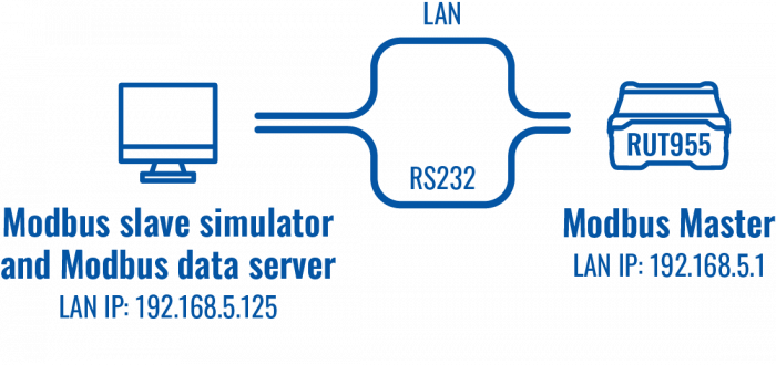
Topology
Configuring Modbus serial slave device
In this example we are going to be using our Windows 10 computer as a slave. To do so you will need to install modRSsim application, which you can download here.
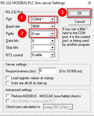
When you are done with that, open the app and apply the following configuration.
- Select Protocol (MODBUS RS-232).
- Click Setup the communication Serial or TCP/IP port.
- Select the Port which you connected RS232 cable to (to find which port you are using go to Windows search bar and write Device Manager then select Ports and see which one you are using).
- Select Parity (Even).
- Click OK.
Configuring Modbus serial master
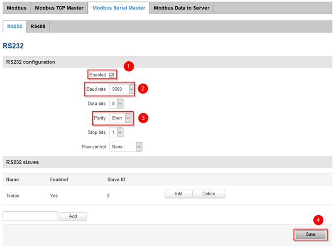
Open router’s WebUI, navigate to Services > Modbus > Modbus Serial Master and apply the following configuration.
- Press Enable.
- Select Baud rate (9600, it must match slave‘s baud rate).
- Select Parity (Even).
- Press Save.
Now create RS232 slave by writing a name, pressing Add button. It should appear like in the example and then press Edit.
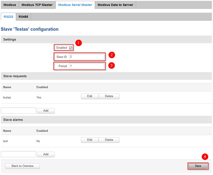
Then apply the following configuration.
- Check Enable.
- Type in Slave ID (any number from 1 to 255).
- Add Period (Query period).
- Press Save.
Go back to the Slave configuration window and create Slave request by writing a name, pressing Add button. It should appear like in the example and then press Edit.
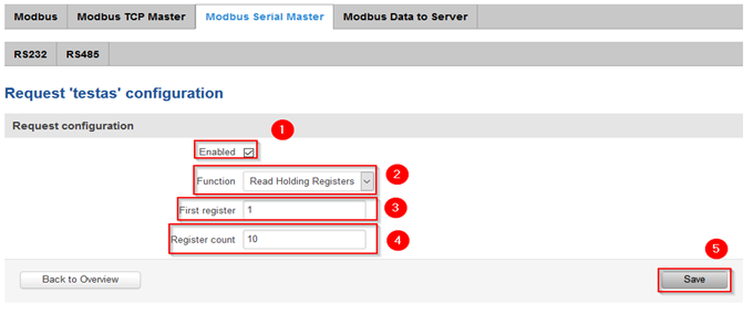
Then apply the following configuration.
- Check Enable.
- Select Function (Read Holding Registers).
- Write First register (1).
- Write Register count (10).
- Press Save.
Modbus data to server
Creating server
In order to test the functionality, you will need to set up a server (you can run a server on the same computer you use as a slave simulator).
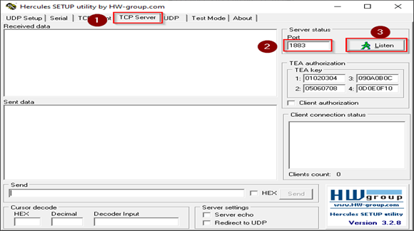
There are many ways how you can create a server to which Modbus will send data to. In this example we are going to be using Windows 10 computer and Hercules app, which you can download here, to create a test server. Download, install the app and apply the configuration below:
- Select TCP Server tab.
- Enter Port (In this example default 1883 is used).
- Click Listen
And that is it, now you will be able to see the data coming from Modbus in the Received data section.
RUT Modbus data to server configuration
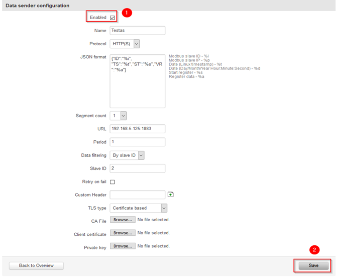
In order to setup your router to send Modbus data to server you will need to navigate to Services > Modbus > Modbus Data to Server.
- Select Protocol (In this example HTTP(S) will be used).
- Enter IP and port of the PC with the Hercules software.
- Enter Period (minutes, how often router should send data to server).
- Click ADD.
Then you will be redirected to Advanced sender settings.
- Enter Name (It can be anything you want).
- Click Save.
Receiving data
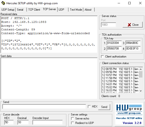
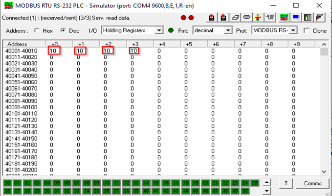
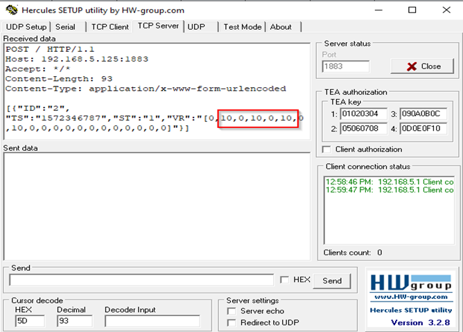
Open Hercules again, press Listen and you should start receiving Modbus Data messages.
Try to change some data in the Modbus Slave simulator.
Received data should change.
Slave alarms
In order to setup the following configuration SIM card is required.
Go back to Services > Modbus > Modbus Serial Master and press edit the same Slave configuration or create a new one. There will be section called Slave alarms. Create a name, then press Add button. When it appears like in the example, press Edit.
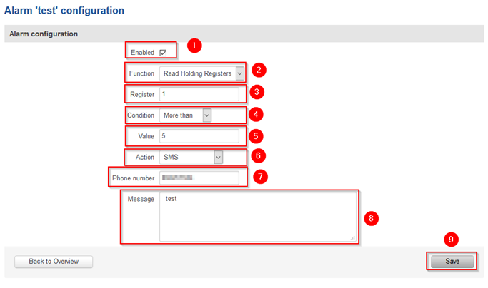
Then apply the following configuration:
- Enable instance.
- Select Function (Read Holding Registers).
- Write Register (1).
- Select Condition (More than).
- Write Value (5).
- Select Action (SMS).
- Write Phone number (the number you want to receive the messages to).
- Create Message (type anything you want to receive).
- Press Save.
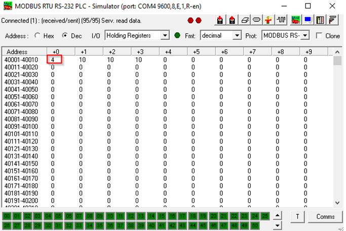
Now go back to Modbus slave simulator and edit this window:
Change the value to anything below 5, you should not receive messages. Then change the value to anything above 5, you should start receiving messages.

