Difference between revisions of "Template:Networking rutos manual usb tools"
| (34 intermediate revisions by 6 users not shown) | |||
| Line 1: | Line 1: | ||
| − | {{Template: | + | {{Template:Networking_rutos_manual_fw_disclosure |
| − | | | + | | fw_version = {{{series}}}_R_00.02.06 |
| − | + | | series = {{{series}}} | |
| − | |||
| − | |||
| − | |||
| − | |||
}} | }} | ||
| − | + | __TOC__ | |
| + | |||
==Summary== | ==Summary== | ||
The <b>USB Tools</b> page is used to manage services related to the device's USB connector. | The <b>USB Tools</b> page is used to manage services related to the device's USB connector. | ||
| − | This | + | This manual page provides an overview of the USB Tools page in {{{name}}} devices. |
{{Template:Networking_rutos_manual_basic_advanced_webui_disclaimer | {{Template:Networking_rutos_manual_basic_advanced_webui_disclaimer | ||
| Line 18: | Line 15: | ||
}} | }} | ||
| − | |||
| − | |||
| − | |||
| − | |||
| − | |||
| − | |||
| − | |||
| − | |||
| − | |||
| − | |||
| − | |||
| − | |||
| − | |||
| − | |||
| − | |||
| − | |||
| − | |||
| − | |||
| − | |||
| − | |||
| − | |||
| − | |||
| − | |||
| − | |||
| − | |||
| − | |||
| − | |||
| − | |||
| − | |||
| − | |||
| − | |||
| − | |||
| − | |||
| − | |||
| − | |||
| − | |||
| − | |||
| − | |||
| − | |||
| − | |||
| − | |||
| − | |||
| − | |||
| − | |||
| − | |||
| − | |||
| − | |||
| − | |||
| − | |||
| − | |||
| − | |||
| − | |||
| − | |||
| − | |||
| − | |||
| − | |||
| − | |||
| − | |||
| − | |||
| − | |||
==Printer Server== | ==Printer Server== | ||
| Line 94: | Line 31: | ||
<tr> | <tr> | ||
<td>Enable</td> | <td>Enable</td> | ||
| − | <td>off | + | <td>off | on; default: <b>off</b></td> |
| − | <td>Turns | + | <td>Turns printer support on or off.</td> |
</tr> | </tr> | ||
<tr> | <tr> | ||
<td>Device</td> | <td>Device</td> | ||
| − | <td> | + | <td>file path; default: <b>/dev/usb/lp0</b></td> |
<td>Printer's device file.</td> | <td>Printer's device file.</td> | ||
</tr> | </tr> | ||
| Line 109: | Line 46: | ||
<tr> | <tr> | ||
<td>Bidirectional mode</td> | <td>Bidirectional mode</td> | ||
| − | <td>off | + | <td>off | on; default: <b>on</b></td> |
<td>Turns bidirectional mode on or off.</td> | <td>Turns bidirectional mode on or off.</td> | ||
</tr> | </tr> | ||
</table> | </table> | ||
| − | + | ||
| − | + | ===PC and printer setup=== | |
| − | + | ---- | |
| + | For step-by-step instructions on how to use a printer with {{{name}}}, <b>[[How to set up a USB printer (Windows, {{{name}}})|click here]]</b> | ||
==USB to Serial== | ==USB to Serial== | ||
| − | The device's USB connector can also be used as a <b>serial port</b>. | + | The device's USB connector can also be used as a <b>serial port</b>. |
[[File:Networking_rutos_manual_usb_tools_printer_server_usb_to_serial.png|border|class=tlt-border]] | [[File:Networking_rutos_manual_usb_tools_printer_server_usb_to_serial.png|border|class=tlt-border]] | ||
| Line 131: | Line 69: | ||
<tr> | <tr> | ||
<td>Enabled</td> | <td>Enabled</td> | ||
| − | <td>off | + | <td>off | on; default: <b>off</b></td> |
<td>Turns the USB to Serial service on or off.</td> | <td>Turns the USB to Serial service on or off.</td> | ||
</tr> | </tr> | ||
<tr> | <tr> | ||
<td>Baud rate</td> | <td>Baud rate</td> | ||
| − | <td>300 | + | <td>300 | 1200 | 2400 | 4800 | 9600 | 19200 | 38400 | 57600 | 115200; default: <b>115200</b></td> |
<td>Data rate for serial data transmission (in bits per second).</td> | <td>Data rate for serial data transmission (in bits per second).</td> | ||
</tr> | </tr> | ||
<tr> | <tr> | ||
<td>Data bits</td> | <td>Data bits</td> | ||
| − | <td>5 | + | <td>5 | 6 | 7 | 8; default: <b>8</b></td> |
<td>Number of data bits for each character</td> | <td>Number of data bits for each character</td> | ||
</tr> | </tr> | ||
<tr> | <tr> | ||
<td>Parity</td> | <td>Parity</td> | ||
| − | <td>None | + | <td>None | Odd | Even; default: <b>None</b></td> |
<td>In serial transmission, parity is a method of detecting errors. An extra data bit is sent with each data character, arranged so that the number of 1 bits in each character, including the parity bit, is always odd or always even. If a byte is received with the wrong number of 1s, then it must have been corrupted. However, an even number of errors can pass the parity check. | <td>In serial transmission, parity is a method of detecting errors. An extra data bit is sent with each data character, arranged so that the number of 1 bits in each character, including the parity bit, is always odd or always even. If a byte is received with the wrong number of 1s, then it must have been corrupted. However, an even number of errors can pass the parity check. | ||
<ul> | <ul> | ||
| Line 157: | Line 95: | ||
<tr> | <tr> | ||
<td>Stop bits</td> | <td>Stop bits</td> | ||
| − | <td>1 | + | <td>1 | 2; default: <b>1</b></td> |
<td>Stop bits sent at the end of every character allow the receiving signal hardware to detect the end of a character and to resynchronise with the character stream. Electronic devices usually use one stop bit. Two stop bits are required if slow electromechanical devices are used.</td> | <td>Stop bits sent at the end of every character allow the receiving signal hardware to detect the end of a character and to resynchronise with the character stream. Electronic devices usually use one stop bit. Two stop bits are required if slow electromechanical devices are used.</td> | ||
</tr> | </tr> | ||
<tr> | <tr> | ||
<td>Flow control</td> | <td>Flow control</td> | ||
| − | <td>None | + | <td>None | RTS/CTS | Xon/Xoff; default: <b>None</b></td> |
<td>In many circumstances a transmitter might be able to send data faster than the receiver is able to process it. To cope with this, serial lines often incorporate a "handshaking" method, usually distinguished between hardware and software handshaking. | <td>In many circumstances a transmitter might be able to send data faster than the receiver is able to process it. To cope with this, serial lines often incorporate a "handshaking" method, usually distinguished between hardware and software handshaking. | ||
<ul> | <ul> | ||
<li><b>RTS/CTS</b> - hardware handshaking. RTS and CTS are turned OFF and ON from alternate ends to control data flow, for instance when a buffer is almost full.</li> | <li><b>RTS/CTS</b> - hardware handshaking. RTS and CTS are turned OFF and ON from alternate ends to control data flow, for instance when a buffer is almost full.</li> | ||
| − | <li><b>Xon/Xoff</b> - software handshaking. The Xon and Xoff characters are sent by the receiver to the sender to control when the sender will send data, i.e., these characters go in the opposite direction to the data being sent. The circuit starts in the "sending allowed" state. When the receiver's buffers approach capacity, the receiver sends the Xoff character to tell the sender to stop sending data. Later, after the receiver has emptied its buffers, it sends an Xon character to tell the sender to resume transmission. | + | <li><b>Xon/Xoff</b> - software handshaking. The Xon and Xoff characters are sent by the receiver to the sender to control when the sender will send data, i.e., these characters go in the opposite direction to the data being sent. The circuit starts in the "sending allowed" state. When the receiver's buffers approach capacity, the receiver sends the Xoff character to tell the sender to stop sending data. Later, after the receiver has emptied its buffers, it sends an Xon character to tell the sender to resume transmission. |
</ul> | </ul> | ||
</td> | </td> | ||
| Line 172: | Line 110: | ||
<tr> | <tr> | ||
<td>Serial type</td> | <td>Serial type</td> | ||
| − | <td>[[#Console|Console]] | + | <td>[[#Console|Console]] | [[#Over IP|Over IP]] | [[#Modbus gateway|Modbus gateway]] | [[#NTRIP client|NTRIP client]]; default: <b>Console</b></td> |
<td>Specifies the serial connection type.<br><b>Look to the sections below for information on different USB to Serial type options.</b></td> | <td>Specifies the serial connection type.<br><b>Look to the sections below for information on different USB to Serial type options.</b></td> | ||
</tr> | </tr> | ||
| Line 197: | Line 135: | ||
<tr> | <tr> | ||
<td>Protocol</td> | <td>Protocol</td> | ||
| − | <td>TCP | + | <td>TCP | UDP; default: <b>TCP</b></td> |
<td>Protocol used in the communication process.</td> | <td>Protocol used in the communication process.</td> | ||
</tr> | </tr> | ||
<tr> | <tr> | ||
<td>Mode</td> | <td>Mode</td> | ||
| − | <td><span style="color: | + | <td><span style="color: red;">Server</span> | <span style="color: purple;">Client</span> | Bidirect; default: <b>Server</b></td> |
| − | <td> | + | <td>This device's role in the connection: |
<ul> | <ul> | ||
| − | <li><b | + | <li><b>Server</b> - the device waits for incoming connections.</li> |
| − | <li><b | + | <li><b>Client</b> - the device initiates the connection.</li> |
| − | <li><b | + | <li><b>Bidirect</b> - acts as client by default but waits for incoming connections at the same time.</li> |
</ul> | </ul> | ||
</td> | </td> | ||
| Line 213: | Line 151: | ||
<tr> | <tr> | ||
<td>No leading zeros</td> | <td>No leading zeros</td> | ||
| − | <td>off | + | <td>off | on; default: <b>off</b></td> |
<td>When checked, indicates that the first hex zeros should be skipped.</td> | <td>When checked, indicates that the first hex zeros should be skipped.</td> | ||
</tr> | </tr> | ||
| Line 228: | Line 166: | ||
<tr> | <tr> | ||
<td><span style="color: red;">Server settings</span>: Open port automatically</td> | <td><span style="color: red;">Server settings</span>: Open port automatically</td> | ||
| − | <td>off | + | <td>off | on; default: <b>on</b></td> |
<td>Automatically adds a traffic rule in the firewall configuration to open the required port for NTRIP communication.</td> | <td>Automatically adds a traffic rule in the firewall configuration to open the required port for NTRIP communication.</td> | ||
</tr> | </tr> | ||
<tr> | <tr> | ||
<td><span style="color: purple;">Client settings</span>: Server Address</td> | <td><span style="color: purple;">Client settings</span>: Server Address</td> | ||
| − | <td>ip | + | <td>ip | host; default: <b>none</b></td> |
<td>IP address or hostname of the server that this client will connect to.</td> | <td>IP address or hostname of the server that this client will connect to.</td> | ||
</tr> | </tr> | ||
| Line 248: | Line 186: | ||
<tr> | <tr> | ||
<td>Echo</td> | <td>Echo</td> | ||
| − | <td>off | + | <td>off | on; default: <b>off</b></td> |
<td>Turn USB to serial echo on or off.</td> | <td>Turn USB to serial echo on or off.</td> | ||
</tr> | </tr> | ||
| Line 277: | Line 215: | ||
<tr> | <tr> | ||
<td>Slave ID configuration type</td> | <td>Slave ID configuration type</td> | ||
| − | <td><span style="color: red;">User defined</span> | + | <td><span style="color: red;">User defined</span> | <span style="color: purple;">Obtained from TCP</span>;<br>default: <b><span style="color: red;">User defined</span></b></td> |
<td>Specifies whether slave IDs are user defined or automatically obtained from TCP.</td> | <td>Specifies whether slave IDs are user defined or automatically obtained from TCP.</td> | ||
</tr> | </tr> | ||
<tr> | <tr> | ||
| − | <td><span style="color: red;">Slave ID</span> | + | <td><span style="color: red;">Slave ID</span> | <span style="color: purple;">Permitted slave IDs</span></td> |
| − | <td><span style="color: red;">integer </span> | + | <td><span style="color: red;">integer </span> | <span style="color: purple;">range of integers</span>;<br>default: <b><span style="color: red;">1</span> or <span style="color: purple;">1-247</span></b></td> |
<td>Specifies the slave ID of range of permitted slave IDs. The way this field is named and its function depends on the value of the ''Slave ID configuration'' field. <br> A range of IDs can be specified by placing a hyphen (<i>-</i>) between two integer numbers. For example, if you permit slave IDs in the range of 10 to 20, you would specify it as: <i>10-20</i><br>You can also specify multiple values that are not connected in a range using commas (<i>,</i>). For example, to specify 6, 50 and 100 as permitted slave IDs, you would have to use: <i>6,50,100</i></td> | <td>Specifies the slave ID of range of permitted slave IDs. The way this field is named and its function depends on the value of the ''Slave ID configuration'' field. <br> A range of IDs can be specified by placing a hyphen (<i>-</i>) between two integer numbers. For example, if you permit slave IDs in the range of 10 to 20, you would specify it as: <i>10-20</i><br>You can also specify multiple values that are not connected in a range using commas (<i>,</i>). For example, to specify 6, 50 and 100 as permitted slave IDs, you would have to use: <i>6,50,100</i></td> | ||
</tr> | </tr> | ||
<tr> | <tr> | ||
<td>Open port automatically</td> | <td>Open port automatically</td> | ||
| − | <td>off | + | <td>off | on; default: <b>on</b></td> |
<td>Automatically adds a traffic rule in the firewall configuration to open the required port for serial communication.<br><b><u>Caution:</u></b> use with care if listening IP is left as the default value (<i>0.0.0.0</i>). Leaving it as such will leave the device open for remote connections on the specified port.</td> | <td>Automatically adds a traffic rule in the firewall configuration to open the required port for serial communication.<br><b><u>Caution:</u></b> use with care if listening IP is left as the default value (<i>0.0.0.0</i>). Leaving it as such will leave the device open for remote connections on the specified port.</td> | ||
</tr> | </tr> | ||
<tr> | <tr> | ||
<td>Echo</td> | <td>Echo</td> | ||
| − | <td>off | + | <td>off | on; default: <b>off</b></td> |
<td>Turn USB to serial echo on or off.</td> | <td>Turn USB to serial echo on or off.</td> | ||
</tr> | </tr> | ||
| Line 321: | Line 259: | ||
<tr> | <tr> | ||
<td>Mount point</td> | <td>Mount point</td> | ||
| − | <td>filepath | + | <td>filepath | string; default: <b>none</b></td> |
<td>NTRIP mount point.</td> | <td>NTRIP mount point.</td> | ||
</tr> | </tr> | ||
<tr> | <tr> | ||
<td>Data format</td> | <td>Data format</td> | ||
| − | <td>NTRIP V2.0 TCP/IP | + | <td>NTRIP V2.0 TCP/IP | NTRIP V2.0 RSTP/RTP | NTRIP V1.0 | Automatic detection | NTRIP V2.0 UDP; default: <b>NTRIP V1.0</b></td> |
<td>Version of NTRIP protocol.</td> | <td>Version of NTRIP protocol.</td> | ||
</tr> | </tr> | ||
| Line 346: | Line 284: | ||
<tr> | <tr> | ||
<td>Use device GPS</td> | <td>Use device GPS</td> | ||
| − | <td>off | + | <td>off | on; default: <b>off</b></td> |
<td>Allows to obtain default NMEA string from the router's GPS device. Only works if GPS service is enabled and location fix is obtained at the time of NTRIP service start.</td> | <td>Allows to obtain default NMEA string from the router's GPS device. Only works if GPS service is enabled and location fix is obtained at the time of NTRIP service start.</td> | ||
</tr> | </tr> | ||
<tr> | <tr> | ||
<td>Open port automatically</td> | <td>Open port automatically</td> | ||
| − | <td>off | + | <td>off | on; default: <b>on</b></td> |
<td>Automatically adds a traffic rule in the firewall configuration to open the required port for serial communication.</td> | <td>Automatically adds a traffic rule in the firewall configuration to open the required port for serial communication.</td> | ||
</tr> | </tr> | ||
<tr> | <tr> | ||
<td>Echo</td> | <td>Echo</td> | ||
| − | <td>off | + | <td>off | on; default: <b>off</b></td> |
<td>Turn USB to serial echo on or off.</td> | <td>Turn USB to serial echo on or off.</td> | ||
</tr> | </tr> | ||
</table> | </table> | ||
| − | |||
| − | === | + | ==Storage Memory Expansion== |
| + | |||
| + | The <b>Storage Memory Expansion</b> function provides the possibility to expand the device's flash memory with a USB Mass Storage Device (MSD) and use the extra memory to install additional software packages. This section provides instruction on how to do just that. However, there are a few prerequisites and warnings to take note of before using memory expansion. | ||
| + | |||
| + | To be eligible for memory expansion, the USB MSD must meet the following restrictions. | ||
| + | |||
| + | <ul> | ||
| + | <li>The MSD must be the last one (chronologically) inserted.</li> | ||
| + | <li>If you are using a USB hub, the target MSD must be the last one attached to the hub.</li> | ||
| + | <li><b>No important data on the MSD as it will be wiped during expansion setup!</b></li> | ||
| + | </ul> | ||
| + | |||
| + | When expansion is enabled, <b>do not detach the USB device as this will delete the data stored on it</b>. Changes made to the device configuration while expansion was enabled will disappear after it is disabled. | ||
| + | |||
| + | ===Enabling memory expansion=== | ||
---- | ---- | ||
| − | + | To successfully expand the flash memory of your device follow the steps described below. | |
| − | [[File: | + | <ol> |
| + | <li>Attach a USB Mass Storage Device (MSD) to the USB connector on the device and go to the Services → Storage Memory Expansion page.</li> | ||
| + | <li>Set the 'Enable storage expansion' slider to 'on' and click 'Save & Apply'.<br>[[File:Networking_rutos_manual_storage_memory_expansion_enable_1.png|border|class=tlt-border]]</li> | ||
| + | <li>You will see a pop-up asking for confirmation. Take note that <u>if you continue from this point on:</u> | ||
| + | <ul> | ||
| + | <li>your <b>USB device's memory will be wiped</b> and formatted to ext2 format;</li> | ||
| + | <li>your device's <b>current configuration will be backed up</b> and restored to this point if the USB drive is removed or memory expansion is disabled;</li> | ||
| + | <li>the entire procedure <b>may take a very long time</b> and includes a reboot at the end; exact time will vary depending on the size of the MSD (larger size will take longer; for example, using a 128 GB drive will take about 2 hours to fully set up, while a 16 GB will only take about 5 minutes).</li> | ||
| + | </ul>Click 'Continue' to proceed.<br>[[File:Networking_rutos_manual_storage_memory_expansion_enable_2.png|border|class=tlt-border]] | ||
| + | </li> | ||
| + | <li>If all is in order you should see a 'Formatting MSD...' message on the screen. This indicates that the MSD is being formatted and integrated with the system. This procedure can take a long time and ends with a reboot of the device.<br>[[File:Networking_rutos_manual_storage_memory_expansion_enable_3.png]]</li> | ||
| + | <li>Your device's flash memory will be expanded once the reboot has finished. In order to check, log in to the WebUI and look to the 'System' widget in the 'Overview' page. Hover your mouse cursor over the 'FLASH' memory indicator; you should see an increase to the device's flash memory.<br>[[File:Networking_rutos_manual_storage_memory_expansion_enable_4.png|border|class=tlt-border]]</li> | ||
| + | </ol> | ||
| − | + | ===Disabling memory expansion=== | |
| + | ---- | ||
| + | To successfully disable memory expansion follow the steps described below. | ||
| − | [[File: | + | <ol> |
| + | <li>Go to the Services → Storage Memory Expansion page.</li> | ||
| + | <li>Set the 'Enable storage expansion' slider to 'off' and click 'Save & Apply'.<br>[[File:Networking_rutos_manual_storage_memory_expansion_disable_1.png|border|class=tlt-border]]</li> | ||
| + | <li>You will see a pop-up asking for confirmation. Take note that <u>if you continue from this point on:</u> | ||
| + | <ul> | ||
| + | <li>your <b>USB device's memory will be wiped</b> and formatted to NTFS format;</li> | ||
| + | <li>your <b>device's configuration will be restored</b> to the point it was before memory expansion;</li> | ||
| + | <li>the entire procedure <b>will take up to 2 minutes</b> including a reboot.</li> | ||
| + | </ul>Click 'Continue' to proceed.<br>[[File:Networking_rutos_manual_storage_memory_expansion_disable_2.png|border|class=tlt-border]] | ||
| + | </li> | ||
| + | <li>If all is in order you should see a 'Formatting MSD...' message on the screen. This indicates that the MSD is being formatted and detached from the system. This procedure can take up to a couple of minutes and ends with a reboot of the device.<br>[[File:Networking_rutos_manual_storage_memory_expansion_disable_3.png]]</li> | ||
| + | <li>Your device's flash memory will be restored to normal once the reboot has finished. In order to check, log in to the WebUI and look to the 'System' widget in the 'Overview' page. Hover your mouse cursor over the 'FLASH' memory indicator; you should see your device's flash memory return to its regular size.<br>[[File:Networking_rutos_manual_storage_memory_expansion_disable_4.png|border|class=tlt-border]]</li> | ||
| + | </ol> | ||
| − | |||
==Network Shares== | ==Network Shares== | ||
| Line 380: | Line 356: | ||
<li>FAT</li> | <li>FAT</li> | ||
<li>FAT32</li> | <li>FAT32</li> | ||
| − | |||
<li>NTFS</li> | <li>NTFS</li> | ||
| − | |||
| − | |||
| − | |||
</ul> | </ul> | ||
| − | + | ||
| − | |||
| − | |||
===General Settings=== | ===General Settings=== | ||
---- | ---- | ||
The <b>General</b> section is used to set up <b>Samba</b> - a software solution for using the Server Message Block (SMB) networking protocol, which provides shared file access between nodes on a computer network. Refer to the figures and table below for more information about Samba configuration. | The <b>General</b> section is used to set up <b>Samba</b> - a software solution for using the Server Message Block (SMB) networking protocol, which provides shared file access between nodes on a computer network. Refer to the figures and table below for more information about Samba configuration. | ||
| − | [[File: | + | [[File:Networking_rutos_manual_usb_tools_network_shares_general_samba_general_settings.png|border|class=tlt-border]] |
<table class="nd-mantable"> | <table class="nd-mantable"> | ||
| Line 403: | Line 373: | ||
<tr> | <tr> | ||
<td>Enable</td> | <td>Enable</td> | ||
| − | <td>off | + | <td>off | on; default: <b>off</b></td> |
<td>Turns Samba on or off.</td> | <td>Turns Samba on or off.</td> | ||
</tr> | </tr> | ||
| Line 423: | Line 393: | ||
<tr> | <tr> | ||
<td>Share home-directories</td> | <td>Share home-directories</td> | ||
| − | <td>off | + | <td>off | on; default: <b>on</b></td> |
<td>Allows system users to reach their home directories via network shares.</td> | <td>Allows system users to reach their home directories via network shares.</td> | ||
| − | |||
| − | |||
| − | |||
| − | |||
| − | |||
| − | |||
| − | |||
| − | |||
| − | |||
| − | |||
</tr> | </tr> | ||
</table> | </table> | ||
| + | |||
| + | ===Edit Template=== | ||
| + | ---- | ||
| + | The <b>Edit Template</b> section is used to make modifications to the template that is used for generating the Samba configuration. This is the content of the <i>/etc/samba/smb.conf.template</i> file from which your Samba configuration will be generated. Values enclosed by pipe symbols ('|') should not be changed. They get their values from the 'General Settings' tab. | ||
| + | |||
| + | [[File:Networking_rutos_manual_usb_tools_network_shares_general_samba_edit_template.png|border|class=tlt-border]] | ||
| + | |||
| + | ===Format USB=== | ||
| + | ---- | ||
| + | The <b>Format USB</b> section contains only one button that is used for formatting an attached USB drive. | ||
| + | |||
| + | [[File:Networking_rutos_manual_usb_tools_network_shares_general_samba_format_usb.png|border|class=tlt-border]] | ||
===Shared Directories=== | ===Shared Directories=== | ||
| Line 467: | Line 439: | ||
<td>Allowed users</td> | <td>Allowed users</td> | ||
<td>samba user(s); default: <b>none</b></td> | <td>samba user(s); default: <b>none</b></td> | ||
| − | <td>Samba user(s) that are permitted to access a | + | <td>Samba user(s) that are permitted to access a shared directory. Users can be created from the Users menu tab.</td> |
</tr> | </tr> | ||
<tr> | <tr> | ||
<td>Read-only</td> | <td>Read-only</td> | ||
| − | <td>off | + | <td>off | on; default: <b>off</b></td> |
| − | <td>Makes a | + | <td>Makes a directory read-only, which means the shared directory can only be accessed to view and read files.</td> |
</tr> | </tr> | ||
<tr> | <tr> | ||
<td>Browseable</td> | <td>Browseable</td> | ||
| − | <td>off | + | <td>off | on; default: <b>on</b></td> |
| − | <td>Makes a Shared Directory browsable; i.e., visible in shared directory | + | <td>Makes a Shared Directory browsable; i.e., visible in network shared directory discovery.</td> |
</tr> | </tr> | ||
<tr> | <tr> | ||
<td>Allow guests</td> | <td>Allow guests</td> | ||
| − | <td>off | + | <td>off | on; default: <b>off</b></td> |
<td>Turns guest access on or off. Guest access allows anonymous connections to a Shared Directory.</td> | <td>Turns guest access on or off. Guest access allows anonymous connections to a Shared Directory.</td> | ||
</tr> | </tr> | ||
| Line 515: | Line 487: | ||
[[File:Networking_rutos_manual_usb_tools_network_shares_users_user_settings.png|border|class=tlt-border]] | [[File:Networking_rutos_manual_usb_tools_network_shares_users_user_settings.png|border|class=tlt-border]] | ||
| − | |||
| − | |||
| − | |||
| − | |||
| − | |||
| − | |||
| − | |||
| − | |||
| − | |||
| − | |||
| − | |||
| − | |||
| − | |||
| − | |||
| − | |||
| − | |||
| − | |||
| − | |||
| − | |||
| − | |||
| − | |||
| − | |||
| − | |||
| − | |||
| − | |||
| − | |||
| − | |||
| − | |||
| − | |||
| − | |||
| − | |||
| − | |||
| − | |||
| − | |||
| − | |||
| − | |||
| − | |||
| − | |||
| − | |||
| − | |||
| − | |||
| − | |||
| − | |||
| − | |||
| − | |||
| − | |||
| − | |||
| − | |||
| − | |||
| − | |||
| − | |||
| − | |||
| − | |||
| − | |||
| − | |||
| − | |||
| − | |||
| − | |||
| − | |||
| − | |||
| − | |||
| − | |||
| − | |||
| − | |||
| − | |||
| − | |||
| − | |||
| − | |||
| − | |||
| − | |||
| − | |||
| − | |||
| − | |||
| − | |||
| − | |||
| − | |||
| − | |||
| − | |||
| − | |||
| − | |||
| − | |||
| − | |||
| − | |||
| − | |||
| − | |||
| − | |||
| − | |||
| − | |||
| − | |||
| − | |||
| − | |||
| − | |||
| − | |||
| − | |||
| − | |||
| − | |||
| − | |||
| − | |||
| − | |||
| − | |||
| − | |||
| − | |||
| − | |||
| − | |||
| − | |||
| − | |||
| − | |||
| − | |||
| − | |||
| − | |||
| − | |||
| − | |||
| − | |||
| − | |||
| − | |||
| − | |||
| − | |||
| − | |||
| − | |||
[[Category:{{{name}}} Services section]] | [[Category:{{{name}}} Services section]] | ||
Revision as of 10:57, 16 November 2020
Template:Networking rutos manual fw disclosure
Summary
The USB Tools page is used to manage services related to the device's USB connector.
This manual page provides an overview of the USB Tools page in {{{name}}} devices.
If you're having trouble finding this page or some of the parameters described here on your device's WebUI, you should turn on "Advanced WebUI" mode. You can do that by clicking the "Advanced" button, located at the top of the WebUI.

Printer Server
The Printer Server feature provides the possibility to configure access to a printer that is connected to the USB port of the device. After the printer is connected to the device's USB port and configured, it can be utilized by users in the local network (LAN, WiFi) or remotely.
The 'Add' button lets you add and manage additional printers. To configure a printer instance, click the Edit button located next to it:

| Field | Value | Description |
|---|---|---|
| Enable | off | on; default: off | Turns printer support on or off. |
| Device | file path; default: /dev/usb/lp0 | Printer's device file. |
| Port | integer [9100..9109]; default: 9100 | Printer's TCP port. |
| Bidirectional mode | off | on; default: on | Turns bidirectional mode on or off. |
PC and printer setup
For step-by-step instructions on how to use a printer with {{{name}}}, [[How to set up a USB printer (Windows, {{{name}}})|click here]]
USB to Serial
The device's USB connector can also be used as a serial port.

| Field | Value | Description |
|---|---|---|
| Enabled | off | on; default: off | Turns the USB to Serial service on or off. |
| Baud rate | 300 | 1200 | 2400 | 4800 | 9600 | 19200 | 38400 | 57600 | 115200; default: 115200 | Data rate for serial data transmission (in bits per second). |
| Data bits | 5 | 6 | 7 | 8; default: 8 | Number of data bits for each character |
| Parity | None | Odd | Even; default: None | In serial transmission, parity is a method of detecting errors. An extra data bit is sent with each data character, arranged so that the number of 1 bits in each character, including the parity bit, is always odd or always even. If a byte is received with the wrong number of 1s, then it must have been corrupted. However, an even number of errors can pass the parity check.
|
| Stop bits | 1 | 2; default: 1 | Stop bits sent at the end of every character allow the receiving signal hardware to detect the end of a character and to resynchronise with the character stream. Electronic devices usually use one stop bit. Two stop bits are required if slow electromechanical devices are used. |
| Flow control | None | RTS/CTS | Xon/Xoff; default: None | In many circumstances a transmitter might be able to send data faster than the receiver is able to process it. To cope with this, serial lines often incorporate a "handshaking" method, usually distinguished between hardware and software handshaking.
|
| Serial type | Console | Over IP | Modbus gateway | NTRIP client; default: Console | Specifies the serial connection type. Look to the sections below for information on different USB to Serial type options. |
Console
Console mode requires no further configuration than the settings above and is used as a direct-access method to the device's shell interface. For this purpose you may want use such applications as PuTTY on Windows and microcom, minicom, picocom or similar applications on Linux.
![]()
Over IP
The Over IP serial type is used to manage serial connections over a TCP/IP network.

| Field | Value | Description |
|---|---|---|
| Protocol | TCP | UDP; default: TCP | Protocol used in the communication process. |
| Mode | Server | Client | Bidirect; default: Server | This device's role in the connection:
|
| No leading zeros | off | on; default: off | When checked, indicates that the first hex zeros should be skipped. |
| Server settings: Port | integer [0..65535]; default: none | Internal port number used to listen for incoming connections. |
| Server settings: Timeout (s) | integer; default: none | Specifies an inactivity time limit (in second) after which an inactive clients is disconnected. |
| Server settings: Open port automatically | off | on; default: on | Automatically adds a traffic rule in the firewall configuration to open the required port for NTRIP communication. |
| Client settings: Server Address | ip | host; default: none | IP address or hostname of the server that this client will connect to. |
| Client settings: Port | integer [0..65535]; default: none | Server's listening port number. |
| Client settings: Reconnect interval (s) | integer; default: none | Time period (in seconds) between reconnection attempts in case a connection fails. |
| Echo | off | on; default: off | Turn USB to serial echo on or off. |
Modbus gateway
The Modbus gateway serial type allows redirecting TCP data coming to a specified port to an RTU specified by the Slave ID. The Slave ID can be specified by the user or be obtained directly from the Modbus header.

| Field | Value | Description |
|---|---|---|
| Listening IP | ip; default: 0.0.0.0 | IP address to listen for incoming connections. The default value (0.0.0.0) means that this device will listen for incoming connections on any interface or IP address. |
| Port | integer [0..65535]; default: 502 | Port number to listen for incoming connections. |
| Slave ID configuration type | User defined | Obtained from TCP; default: User defined |
Specifies whether slave IDs are user defined or automatically obtained from TCP. |
| Slave ID | Permitted slave IDs | integer | range of integers; default: 1 or 1-247 |
Specifies the slave ID of range of permitted slave IDs. The way this field is named and its function depends on the value of the Slave ID configuration field. A range of IDs can be specified by placing a hyphen (-) between two integer numbers. For example, if you permit slave IDs in the range of 10 to 20, you would specify it as: 10-20 You can also specify multiple values that are not connected in a range using commas (,). For example, to specify 6, 50 and 100 as permitted slave IDs, you would have to use: 6,50,100 |
| Open port automatically | off | on; default: on | Automatically adds a traffic rule in the firewall configuration to open the required port for serial communication. Caution: use with care if listening IP is left as the default value (0.0.0.0). Leaving it as such will leave the device open for remote connections on the specified port. |
| Echo | off | on; default: off | Turn USB to serial echo on or off. |
NTRIP client
Networked Transport of RTCM via Internet Protocol (NTRIP) is a protocol for streaming differential GPS (DGPS) data over the Internet in accordance with specification published by RTCM.

| Field | Value | Description |
|---|---|---|
| IP address | ip; default: 0.0.0.0 | IP address of an NTRIP server. |
| Port | integer [0..65535]; default: none | TCP/UDP port used for NTRIP communication. |
| Mount point | filepath | string; default: none | NTRIP mount point. |
| Data format | NTRIP V2.0 TCP/IP | NTRIP V2.0 RSTP/RTP | NTRIP V1.0 | Automatic detection | NTRIP V2.0 UDP; default: NTRIP V1.0 | Version of NTRIP protocol. |
| Username | string; default: none | Username for authentication to an NTRIP server. |
| Password | string; default: none | Password for authentication to an NTRIP server. |
| Default NMEA string | string; default: none | Optional NMEA string that will be used as the default value when initiating the connection to the NTRIP server (this value is only sent to the server if there is no NMEA from router's GPS device). |
| Use device GPS | off | on; default: off | Allows to obtain default NMEA string from the router's GPS device. Only works if GPS service is enabled and location fix is obtained at the time of NTRIP service start. |
| Open port automatically | off | on; default: on | Automatically adds a traffic rule in the firewall configuration to open the required port for serial communication. |
| Echo | off | on; default: off | Turn USB to serial echo on or off. |
Storage Memory Expansion
The Storage Memory Expansion function provides the possibility to expand the device's flash memory with a USB Mass Storage Device (MSD) and use the extra memory to install additional software packages. This section provides instruction on how to do just that. However, there are a few prerequisites and warnings to take note of before using memory expansion.
To be eligible for memory expansion, the USB MSD must meet the following restrictions.
- The MSD must be the last one (chronologically) inserted.
- If you are using a USB hub, the target MSD must be the last one attached to the hub.
- No important data on the MSD as it will be wiped during expansion setup!
When expansion is enabled, do not detach the USB device as this will delete the data stored on it. Changes made to the device configuration while expansion was enabled will disappear after it is disabled.
Enabling memory expansion
To successfully expand the flash memory of your device follow the steps described below.
- Attach a USB Mass Storage Device (MSD) to the USB connector on the device and go to the Services → Storage Memory Expansion page.
- Set the 'Enable storage expansion' slider to 'on' and click 'Save & Apply'.

- You will see a pop-up asking for confirmation. Take note that if you continue from this point on:
- your USB device's memory will be wiped and formatted to ext2 format;
- your device's current configuration will be backed up and restored to this point if the USB drive is removed or memory expansion is disabled;
- the entire procedure may take a very long time and includes a reboot at the end; exact time will vary depending on the size of the MSD (larger size will take longer; for example, using a 128 GB drive will take about 2 hours to fully set up, while a 16 GB will only take about 5 minutes).

- If all is in order you should see a 'Formatting MSD...' message on the screen. This indicates that the MSD is being formatted and integrated with the system. This procedure can take a long time and ends with a reboot of the device.
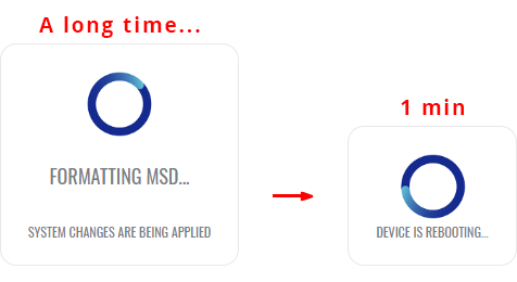
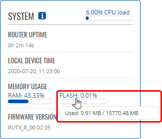
- Your device's flash memory will be expanded once the reboot has finished. In order to check, log in to the WebUI and look to the 'System' widget in the 'Overview' page. Hover your mouse cursor over the 'FLASH' memory indicator; you should see an increase to the device's flash memory.


Disabling memory expansion
To successfully disable memory expansion follow the steps described below.
- Go to the Services → Storage Memory Expansion page.
- Set the 'Enable storage expansion' slider to 'off' and click 'Save & Apply'.

- You will see a pop-up asking for confirmation. Take note that if you continue from this point on:
- your USB device's memory will be wiped and formatted to NTFS format;
- your device's configuration will be restored to the point it was before memory expansion;
- the entire procedure will take up to 2 minutes including a reboot.

- If all is in order you should see a 'Formatting MSD...' message on the screen. This indicates that the MSD is being formatted and detached from the system. This procedure can take up to a couple of minutes and ends with a reboot of the device.
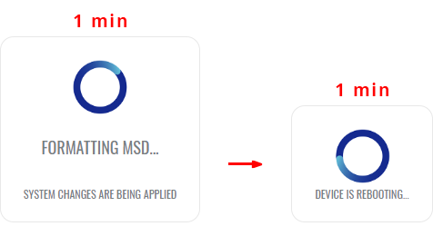
- Your device's flash memory will be restored to normal once the reboot has finished. In order to check, log in to the WebUI and look to the 'System' widget in the 'Overview' page. Hover your mouse cursor over the 'FLASH' memory indicator; you should see your device's flash memory return to its regular size.


The Network Shares section is used to manage Network-attached storage (NAS) such as USB drives and hard drives. The {{{name}}} device supports the following file system architectures:
- FAT
- FAT32
- NTFS
General Settings
The General section is used to set up Samba - a software solution for using the Server Message Block (SMB) networking protocol, which provides shared file access between nodes on a computer network. Refer to the figures and table below for more information about Samba configuration.

| Field | Value | Description |
|---|---|---|
| Enable | off | on; default: off | Turns Samba on or off. |
| Hostname | string; default: Router_share | Name of the Samba server. |
| Description | string; default: Router share | Short description about the Same server. |
| Workgroup | string; default: WORKGROUP | Name of the server's workgroup. |
| Share home-directories | off | on; default: on | Allows system users to reach their home directories via network shares. |
Edit Template
The Edit Template section is used to make modifications to the template that is used for generating the Samba configuration. This is the content of the /etc/samba/smb.conf.template file from which your Samba configuration will be generated. Values enclosed by pipe symbols ('|') should not be changed. They get their values from the 'General Settings' tab.

Format USB
The Format USB section contains only one button that is used for formatting an attached USB drive.

The Shared Directories section is used to configure access to the device's files and directories, including USB storage drives. The list of Shared Directories is empty by default; click the 'Add' button in order to create a new configuration:

The newly added Shared Directory configuration should look similar to this:

| Field | Value | Description |
|---|---|---|
| Name | string; default: none | Name of a shared directory. |
| Path | filepath; default: /mnt/ | Path to a shared directory. To share an entire drive, choose an automatically generated path from this drop-down box (for example, /mnt/sda1). To share a specific directory on the drive, specify the full path to that directory (for example, /mnt/sda1/shared/video). |
| Allowed users | samba user(s); default: none | Samba user(s) that are permitted to access a shared directory. Users can be created from the Users menu tab. |
| Read-only | off | on; default: off | Makes a directory read-only, which means the shared directory can only be accessed to view and read files. |
| Browseable | off | on; default: on | Makes a Shared Directory browsable; i.e., visible in network shared directory discovery. |
| Allow guests | off | on; default: off | Turns guest access on or off. Guest access allows anonymous connections to a Shared Directory. |
| Delete | -(interactive button) | Deletes a Shared Directory configuration. |
To connect to the router's SAMBA server from Windows, specify the address in this format:
\\smb_server_address\share_name
Replace smb_server_address with the IP address of this device or SAMBA share hostname; replace share_name with the name of the "share" (as specified in the 'Name' field). For example:
\\192.168.1.1\my_share
\\Router_share\johns_files
Users
The Users section is used to create Samba users that can be granted access to Shared Directories. To add a new user, enter a custom username, password and click the 'Add' button.

The newly added User should appear in the Users list. To change the password of a Samba User, click the 'Edit' button located next to it:

This will redirect you to the Settings page for that User which should look similar to this:

[[Category:{{{name}}} Services section]]

