RUT955 Input/Output: Difference between revisions
No edit summary |
No edit summary |
||
| (7 intermediate revisions by 5 users not shown) | |||
| Line 1: | Line 1: | ||
{{Template: | {{Template: Networking_rut_manual_input_output | ||
<!------------------------DEVICE-----------------------> | <!------------------------DEVICE-----------------------> | ||
| name | | name = RUT955 | ||
| series | | series = RUT9XX | ||
<!---------------------- | <!------------------------FILES------------------------> | ||
<!--------------------------------STATUS--------------------------------> | |||
| | | file_status = Networking_rut955_manual_input_output_status_io_status_v2.png | ||
| | | file_status_digital = Networking_rutxxx_manual_input_output_status_custom_label_digital_input_v1.png | ||
| file_status_analog = Networking_rut955_manual_input_output_status_custom_label_analog_input_v1.png | |||
<!--------------------------------INPUT---------------------------------> | |||
| file_input_analog = Networking_rut955_manual_input_output_input_check_analog_v1.png | |||
| file_input_add = Networking_rutxxx_manual_input_output_input_input_rules_add_new_v1.png | |||
| file_input_config = Networking_rut955_manual_input_output_input_input_rules_input_configuration_v2.png | |||
| | <!--------------------------------OUTPUT--------------------------------> | ||
| | | file_output_config = Networking_rut955_manual_input_output_output_output_configuration_v2.png | ||
| | | file_output_on_off = Networking_rut955_manual_input_output_output_on_off_v1.png | ||
| | | file_output_post_get = Networking_rutxxx_manual_input_output_output_post_get_configuration_v1.png | ||
| file_output_periodic = Networking_rut955_manual_input_output_output_periodic_control_v1.png | |||
| file_output_scheduler = Networking_rut955_manual_input_output_output_scheduler_v1.png | |||
}} | }} | ||
==Additional Information== | |||
Input/Output hardware application examples: | |||
<ul> | |||
<li><b>[[RUT955 Relay to Open Collector Output|Relay to Open Collector Output]]</b></li> | |||
<li><b>[[RUT955 Inverting Relay Output Polarity|Inverting Relay Output Polarity]]</b></li> | |||
<li><b>[[RUT955 Inputs in Security Applications|Inputs in Security Applications]]</b></li> | |||
<li><b>[[RUT955 Current Measurement with Analog Input|Current Measurement with Analog Input]]</b></li> | |||
</ul> | |||
Revision as of 11:35, 20 November 2020
Main Page > EOL Products > RUT955 > RUT955 Manual > RUT955 WebUI > RUT955 Services section > RUT955 Input/OutputThe information in this page is updated in accordance with firmware version RUT9XX_R_00.06.09.5.
Summary
Inputs and Outputs are used for the monitoring and controlling of a connected device or receiving signals from that device in order to trigger certain events.
This chapter of the user manual provides an overview of the Input/Output page for RUT955 devices.
Characteristics
This section provides a list Input/Output electric characteristics inherent in RUT955 routers.
- Digital input (DIN1): Logic low 0 - 1.2 V; Logic high 1.8 - 3 V
- Digital galvanically isolated input (DIN2): 0 - 30 V
- Analog input (voltage mode): 0 – 24 V*
- Analog input (current mode): up to 20 mA (commonly used with 4-20 mA standard sensors)
- Digital open collector (OC) output: 30 V, 250 mA
- SPST relay output: 24 V, 4 A
- Digital non-isolated input (in power socket): Logic low 0 - 5 V; Logic high 8 - 40 V
- Digital open collector (in power socket) output: 30 V, 300 mA
* The deviation from the actual input voltage and the voltage measured by the device is dependent on the input voltage value:
- ≥ 1.5 V - the deviation is about ± 10 % and gets lower when the input voltage increases towards 5 V
- ≥ 5 V - the deviation does not exceed ± 3 %
- ≥ 9 V - the deviation does not exceed ± 2 %
Additional note: the deviation values specified above are applicable in temperatures of < 50 °C. Under higher temperatures the deviation values become considerably higher.
Status
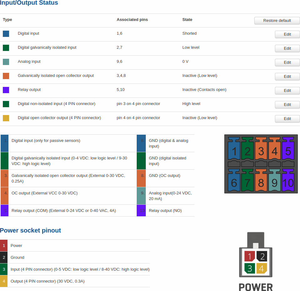
The Status tab displays the current states the router’s inputs and outputs:
Custom Labels
If the default Input/Output labels do not suit your needs, you can always configure custom ones in the Custom Labels section. Click the 'Edit' button next to the desired Input or Output and you will be redirected to a window such as this:
The figure above is an example of custom label configuration for Digital Input. You can change an input's/output's name and the names of their states. The changes are purely cosmetic and used for easier management purposes.
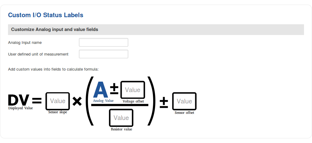
In addition to adding custom names, you can also define how the displayed value for Analog Input is calculated and displayed. The figure below represents what the configuration of custom labels for Analog Input looks like.
Status and control from command line
You can control and monitor input and output values via a command line interface (CLI) with the gpio.sh command. You can execute this command without any additional options to get usage syntax examples:
root@Teltonika:~# gpio.sh
GPIO control aplication
        Usage: /sbin/gpio.sh <ACTION> <NAME>
        ACTION - set, clear, get, export, invert, dirout, dirin
        NAME - SIM      DOUT1   DOUT2   DIN1    DIN2    MON     MRST    SDCS    RS485_R
Where:
- DOUT1 - Digital OC output
- DOUT2 - Digital relay output
- DIN1 - Digital input
- DIN2 - Digital galvanically isolated input
For example, to get the status of the digital OC output use the following command:
root@Teltonika:~# gpio.sh get DOUT1
0
The return value 0 means that the output is in Inactive (High level), i.e., OFF.
You can turn it ON (Active (Low level)) by setting its value to 1:
root@Teltonika:~# gpio.sh invert DOUT1
root@Teltonika:~# gpio.sh get DOUT1
1
As seen in the example above, you can change the value of an output by using the invert command, which simply turns the current value of the specified output into its opposite state.
To get the value of the analog input use the cat /sys/class/hwmon/hwmon0/device/in0_input command. Router will show voltage value in mV. For example:
root@Teltonika:~# cat /sys/class/hwmon/hwmon0/device/in0_input
950
Input
The Input tab is used to configure the router's input pins.
Check Analog
The Check Analog section is used to set how often the router checks the value of the analog input. This is relevant to input rules related to the analog input. For example, if you have configured an input rule that triggers a certain action when the analog input value is inside a certain range, the frequency at which the router will check this value is set in this section.
Input Rules
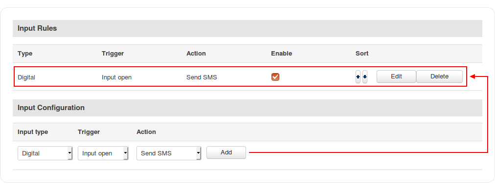
The Input Rules section provides you with the possibility to set up rules that execute user specified actions after a certain trigger occurs. To add a new rule, look to the Input Configuration section that is just below. Select the input, the trigger and the action for the rule and click the 'Add' button. A new rule will appear in the Input Rules list:
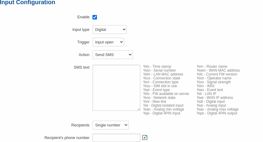
To begin editing an input rule, click the 'Edit' button located next to it. Refer to the figure and table below for information on input rule configuration.
| Field | Value | Description |
|---|---|---|
| Enable | yes | no; default: yes | Turns the input rule on or off. |
| Input type | Digital | Digital isolated | Analog; default: Digital | Selects to which input pin the rule will apply. |
| Trigger | Input open | Input shorted | Both; default: Input open | Selects which input state will trigger the rule. |
| Action | Send SMS | Change SIM card | Send email | Change profile | Turn on WiFi | Turn off WiFi | Reboot | Activate output | HTTP POST/GET; default: Send SMS | The action that will be taken when the rule is triggered.
|
Output
The Output tab is used to configure the router's output pins.
Output Configuration
The Output Configuration section is used to change the default states of the router's output pins.
| Field | Value | Description |
|---|---|---|
| Open collector output | Low level | High level; default: Low level | Changes the default* state of the open collector (OC) output pin. |
* Changing the default state of an output means that the changes will be written into the input/output config and saved. This means that unless some other related change occurs the state of the output will remain as set in this section.
ON/OFF
The ON/OFF section is used to turn the router's outputs on or off. This action does not save the state permanently, meaning that after a reboot the states will revert back to their default values.
Periodic control
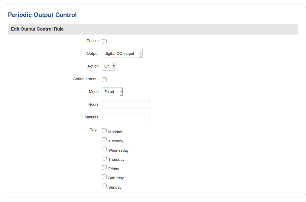
The Periodic control section allows you to set up automatic output control rules that trigger output state changes at the specified period or interval. Refer to the figure and table below for information on configuration fields contained in that section.
| Field | Value | Description |
|---|---|---|
| Enable | yes | no; default: no | Turns the rule on or off. |
| Output | Digital OC Output| Digital 4PIN | Digital relay output; default: Digital OC Output | The output pin that will be effected by the rule. |
| Action | On | Off; default: On | The action that will be performed on the output. |
| Action timeout | yes | no; default: no | Action timeout specifies whether an action should end after some time. For example, if action is set to on and timeout is set to 10, when the trigger occurs the output will turn on for 10 seconds before turning off. |
| Mode | Fixed | Interval; default: Fixed | When the rule will be triggered.
|
Scheduler
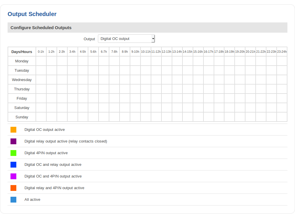
With the help of the output Scheduler you can configure a timetable of when the outputs should be enabled or disabled based on time.
Post/Get
Enabling Post/Get will allow you to send HTTP POST/GET requests to the router that control the state of the output. The figure below is an example of the Post/Get configuration section and the table below provides information on the fields contained in that section:
| Field | Value | Description |
|---|---|---|
| Enable | yes | no; default: no | Turns Post/Get on or off. |
| Username | string; default: none | Username used for authentication in POST/GET queries. |
| Password | string; default: none | Password used for authentication in POST/GET queries. |
Post/Get examples
It is possible to turn the outputs on and off by using a HTTP POST/GET requests. Use a web browser or any other compatible software to send HTTP POST/GET requests to the device.
Below is a table containing syntax examples of this usage:
| Action | POST/GET URL |
|---|---|
| Turn relay output on | http://192.168.1.1/cgi-bin/output?username=user1&password=user1&action=on&pin=relay |
| Turn relay output on after a 10 second delay | http://192.168.1.1/cgi-bin/output?username=user1&password=user1&action=on&pin=relay&delay=10 |
| Turn relay output on for 5 seconds | http://192.168.1.1/cgi-bin/output?username=user1&password=user1&action=on&pin=relay&time=5 |
| Turn Relay output on for 5 seconds after a 15 second delay | http://192.168.1.1/cgi-bin/output?username=user1&password=user1&action=on&pin=relay&delay=15&time=5 |
| Turn relay output off for 5 seconds after a 15 second delay | http://192.168.1.1/cgi-bin/output?username=user1&password=user1&action=off&pin=relay&delay=15&time=5 |
| Turn open collector output on | http://192.168.1.1/cgi-bin/output?username=user1&password=user1&action=on&pin=oc |
| Turn open collector output off | http://192.168.1.1/cgi-bin/output?username=user1&password=user1&action=off&pin=oc |
| Turn Digital 4 PIN output on | http://192.168.1.1/cgi-bin/output?username=user1&password=user1&action=on&pin=4pin |
| Turn Digital 4 PIN output off | http://192.168.1.1/cgi-bin/output?username=user1&password=user1&action=off&pin=4pin |
Overview:
- 192.168.1.1 - router's default LAN IP address; replace it in accordance with your own configuration.
- username - login name from Post/Get configuration.
- password- password from Post/Get configuration.
- action- the action that will be performed on the output (can be on or off).
- pin - specifies the output (use ocor relay).
- delay - defines a delay (in seconds) after which the specified action will be performed.
- time - defines a window of time during which the action will take place. For instance, if you post an on action while specifying time=5, the output will turn on and stay on for 5 seconds before turning off.
Delay and time parameters can be used together. For example, if delay is 10, time is 5, action is on, then 10 seconds after the execution of the command, the output will switch to on (or stay in on state if it was already that way), then after 5 more seconds it will switch to off state. In this case the overall command execution time is 15 seconds.
Additional Information
Input/Output hardware application examples:

