TRB500 Routing: Difference between revisions
Gytispieze (talk | contribs) (Created page with "{{Template: Networking_rutos_manual_routing <!------------------------DEVICE-----------------------> | name = TRB500 | series = TRB5 <!----------------------SEPARATORS----...") |
Gytispieze (talk | contribs) m (Gytispieze moved page Draft:TRB500 Routing to TRB500 Routing without leaving a redirect) |
(No difference)
| |
Latest revision as of 10:20, 5 September 2022
Main Page > TRB Gateways > TRB500 > TRB500 Manual > TRB500 WebUI > TRB500 Network section > TRB500 RoutingThe information in this page is updated in accordance with firmware version TRB5_R_00.07.10.2
Note: Firmware versions before TRB5_R_00.07.04.4 will not be supported by devices from batch 09 and higher..
Summary
The Routing page is used to set up static and dynamic routes, routing tables and rules.
This manual page provides an overview of the Routing windows in TRB500 devices.
If you're having trouble finding this page or some of the parameters described here on your device's WebUI, you should turn on "Advanced WebUI" mode. You can do that by clicking the "Advanced" button, located at the top of the WebUI.
Static Routes
Routes ensure that network traffic finds its path to a specified host or network, both in local and remote network scenarios. Static routes are simply fixed routing entries in the routing table(s).
This section provides the possibility to configure custom static routes.
Static IPv4 Routes
The Static IPv4 Routes section displays a list of user defined static IPv4 routes and provides the possibility to add and configure new ones. The list is empty by default.
To add a new route and begin editing, simply click the 'Add' button. Refer to the table below for information on static route configuration fields.
| Field | Value | Description |
|---|---|---|
| Interface | network interface; default: lan | Network interface of the target network. |
| Target* | ip4; default: none | Destination network address. |
| IPv4-Netmask* | netmask; default: none | A netmask is used to divide an IP address into sub-networks (subnets). Combined together, the 'Netmask' and 'Target' values define the exact destination network or IP address to which this route applies. |
| IPv4-Gateway | ip4; default: none | A gateway can be any machine in a network that is capable of serving as an access point to another network. Traffic that matches this route will be directed over the IP address specified in this field. |
| Metric | integer [0..255]; default: none | The metric value acts as a measurement of priority. If a packet about to be routed matches two or more rules, the one with the lower metric is applied. |
| MTU | integer [64..9000]; default: 1500 | Sets the maximum transmission unit (MTU) size. It is the largest size of a protocol data unit (PDU) that can be transmitted in a single network layer transaction. |
| Route Type | unicast | local | broadcast | multicast | unreachable | prohibit | backhole | anycast | -- custom -- ; default: unicast | Selects route type. Each type specifies a different behavior for the route:
|
*Additional notes on 'Target' & 'Netmask' fields:
You can define a rule that applies to a single IP like this:
- Target: some IP
- Netmask: 255.255.255.255
Furthermore, you can create target/netmask combinations that apply to a range of IPs. Refer to the table below for examples.
| Target | Netmask | Network range |
|---|---|---|
| 192.168.2.0 | 255.255.255.240 | 192.168.2.0 - 192.168.2.15 |
| 192.168.2.240 | 255.255.255.240 | 192.168.2.240 - 192.168.2.255 |
| 192.168.2.161 | 255.255.255.0 | 192.168.2.0 - 192.168.55.255 |
| 192.168.0.0 | 255.255.0.0 | 192.168.0.0 - 192.168.255.255 |
| 192.168.2.161 | 255.255.255.255 | 192.168.2.161 |
Static IPv6 Routes
The Static IPv6 Routes section displays a list of user defined static IPv6 routes and provides the possibility to add and configure new ones. The list is empty by default.
To add a new route and begin editing, simply click the 'Add' button. Refer to the table below for information on static route configuration fields.
| Field | Value | Description |
|---|---|---|
| Interface | network interface; default: lan | Network interface of the target network. |
| Target | ip6; default: none | Destination network address. |
| IPv6-Gateway | ip6; default: none | A gateway can be any machine in a network that is capable of serving as an access point to another network. Traffic that matches this route will be directed over the IP address specified in this field. |
| Metric | integer [0..255]; default: none | The metric value acts as a measurement of priority. If a packet about to be routed matches two or more rules, the one with the lower metric is applied. |
| MTU | integer [64..9000]; default: 1500 | Sets the maximum transmission unit (MTU) size. It is the largest size of a protocol data unit (PDU) that can be transmitted in a single network layer transaction. |
| Route Type | unicast | local | broadcast | multicast | unreachable | prohibit | backhole | anycast | -- custom -- ; default: unicast | Selects route type. Each type specifies a different behavior for the route:
|
Policy Based Routing
The Policy Based Routing section is used to configure policy-based routing infrastructures, which are usually used in more complex or specific networking scenarios.
Routing Tables
Routing Tables store network routes. Tables are checked before every routing decision until a matching route is found. Having multiple tables allows the user to set up a policy routing infrastructure. Policy-based routing is a technique where routing decisions are based on policies (rule) set by the user.
The 'Routing Tables' section displays user created routing tables. By default, the list is empty.
To create a new table, look to the 'Add New Routing Table' section below. Enter an ID for the new table in the range of [1..252], enter a custom name and click the 'Add' button. The new table should appear in the 'Routing Tables' list. Click the 'Edit' button next to it to begin editing.
Refer to the table below for information on configuration fields for routing tables.
| Field | Value | Description |
|---|---|---|
| Name of Table | string; default: none | A custom name for the table. A table can be invoked by the both its ID or name. |
| ID of Table | integer [1..252]; default: none | Unique numerical identifier for the table. A table can be invoked by the both its ID or name. |
Routing Rules For IPv4
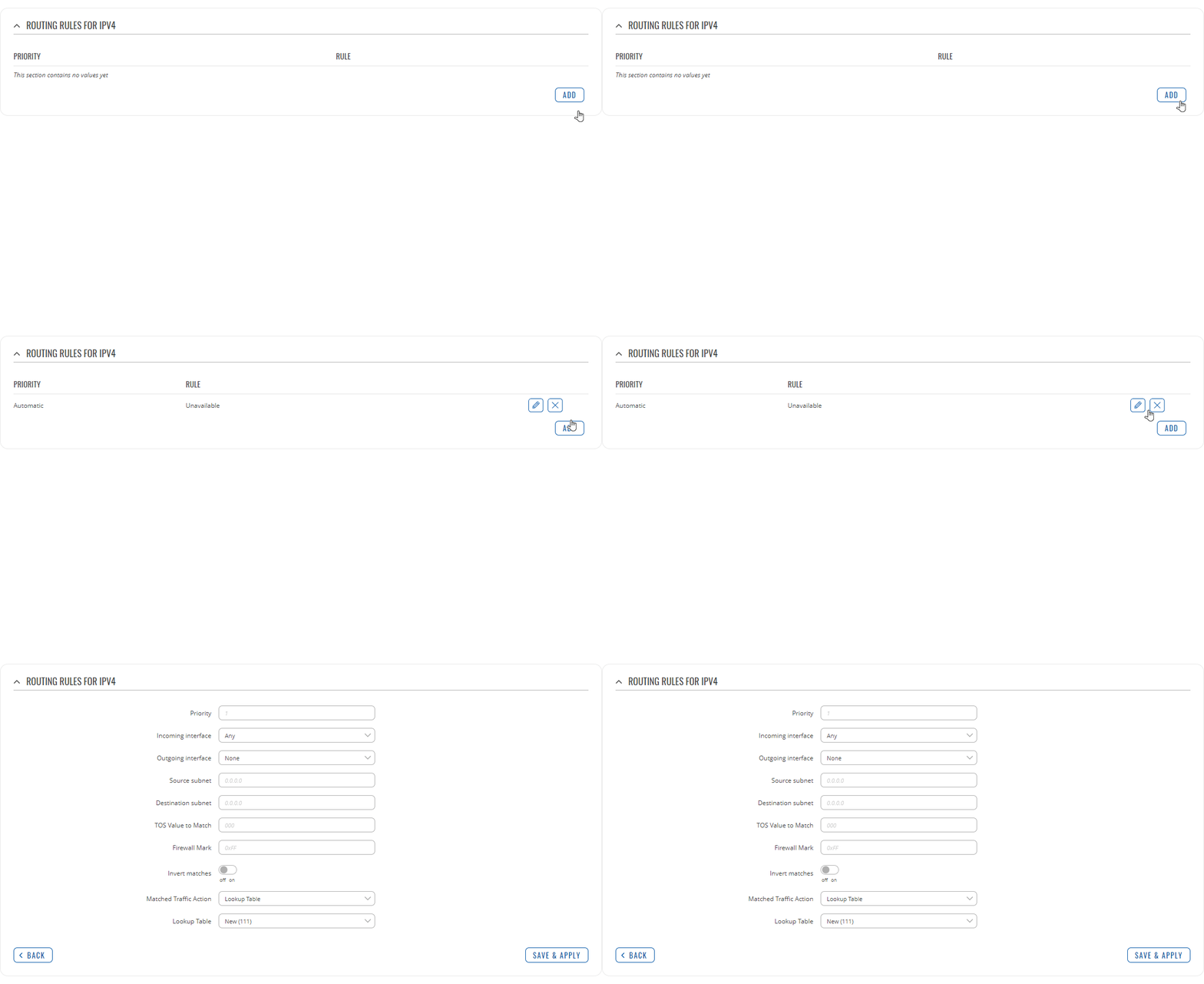
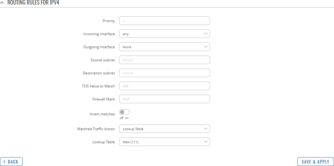
Routing Rules provide a way to route certain packets with exceptions, i.e., in accordance to a rule. 'Routing Rules For IPv4' displays user defined routing rules. It is empty by default. To create a new rule, click the 'Add' button and begin editing by clicking the 'Edit' button located to the right of the newly created rule.
Refer to table below for information on each configuration field.
| Field | Value | Description |
|---|---|---|
| Priority | integer [0..65535]; default: none | Controls the order of IP rules. Rules with a lower priority value will be checked first. |
| Incoming interface | network interface | Any; default: Any | Logical interface name for incoming traffic. Select 'Any' to make the rule apply to all network interfaces. |
| Outgoing interface | network interface | None; default: None | Logical interface name for incoming traffic. Select 'None' to ignore outgoing interface. |
| Source subnet | netmask; default: none | Source subnet to match the rule. |
| Destination subnet | netmask; default: none | Destination subnet to match the rule. |
| TOS Value to Match | integer [0..255]; default: none | The type of service (ToS) value to match in IP headers. |
| Firewall Mark | integer [0..255] | hex [0x00..0xFF]; default: none | Specifies the fwmark and optionally its mask to match. For example, 0xFF to match mark 255 or 0x0/0x1 to match any even mark value. |
| Invert matches | off | on; default: off | If enabled, the meaning of the match options (Firewall Mark, TOS Value, Source and Destination subnets) is inverted. |
| Matched Traffic Action | Lookup Table | Jump to rule | Routing Action; default: Lookup Table | When network traffic matches this rule, the device will take an action specified in this field:
|
| Lookup Table | routing table; default: none | Specifies a table for routing traffic that matches this rule. This field is visible only when 'Matched Traffic Action' is set to Lookup Table. |
| Jump to rule | rule priority number; default: none | Specifies a another rule to follow for traffic that matches this rule. This field is visible only when 'Matched Traffic Action' is set to Jump to rule. |
| Routing Action | Prohibit | Unreachable | Blackhole | Throw; default: Prohibit | When traffic matches this rule, the action specified in this field will be executed. This field is visible only when 'Matched Traffic Action' is set to Routing Action. |
Dynamic Routes
Dynamic Routing provides the possibility to route data based on current network or device state instead of relying on static entries in the routing table. The TRB500 device supports these dynamic routing protocols:
- BGP (Border Gateway Protocol)
- RIP (Routing Information Protocol)
- OSPF (Open Shortest Path First)
- EIGRP (Enhanced Interior Gateway Routing Protocol)
- NHRP (Next Hop Resolution Protocol)
Each protocol is described in the sections below.
Note: Dynamic Routing is additional software that can be installed from the System → Package Manager page.
BGP
The Border Gateway Protocol (BGP) is a standardized exterior gateway protocol designed to exchange routing and reachability information among autonomous systems (AS) on the Internet. The protocol is often classified as a path vector protocol but is sometimes also classed as a distance-vector routing protocol. The Border Gateway Protocol makes routing decisions based on paths, network policies, or rule-sets configured by a network administrator and is involved in making core routing decisions.
General Settings
The General Settings section is used to turn BGP protocol usage on or off or to upload an external BGP configuration. Below is an example of the BGP General Settings section.
| Field | Value | Description |
|---|---|---|
| Enable | off | on; default: off | Turns BGP protocol usage on or off. |
| Enable vty | off | on; default: off | Turns vty access on or off. |
| Import config | - (interactive button) | Uploads an external BGP configuration. |
BGP Instance
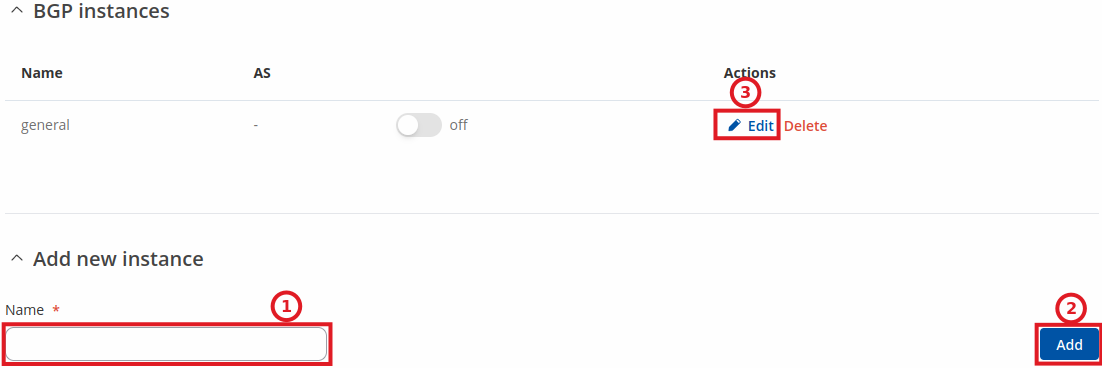
To create a new BGP instance, look to the Add New Instance section under BGP instances; type in a custom name for the BGP instance and click the 'Add' button or you can 'Edit' a general instance:
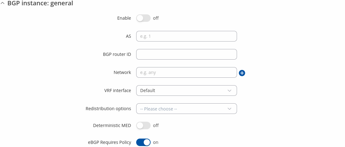
You will be redirected to general BGP instance settings:
| Field | Value | Description |
|---|---|---|
| Enable | off | on; default: off | Turns the BGP instance on or off. |
| AS | integer [1..4294967295]; default: none | AS number is an identification of an autonomous system. BGP protocol uses the AS number for detecting whether the BGP connection is an internal one or external one. |
| BGP router ID | 32-bit integer; default: none | The router ID is used by BGP to identify the routing device from which a packet originated. Default router ID value is selected as the largest IP Address of the interface. |
| Network | ip/netmask; default: none | Adds an announcement network(s). Routes to these networks will be shared over BGP. |
| VRF interface | VRF interface; default: Default | To create new VRF interface, please visit: VRF |
| Redistribution options | Connected routes | Kernel added routes | NHRP routes | OSPF routes | Static routes | custom; default: none | Distributes selected routes. Route redistribution is a process that allows a network to use a routing protocol to dynamically route traffic based on information learned from a separate routing protocol. |
| Deterministic MED | off | on; default: off | Compares MEDs between same AS, while ignoring their age. |
| eBGP Requires Policy | off | on; default: on | Enable/Disable eBGP Import or Export policy requirement. Enabled by default as per RFC 8212. |
BGP Peers
BGP Peers are routers in the same BGP Peer Group that can redistribute routes among other BGP Peers. Below is an example of the BGP Peers section, which is empty by default.
To create a new Peer, look to the Add New Instance section under BGP Peer; type in a custom name for the BGP Peer and click the 'Add' button:
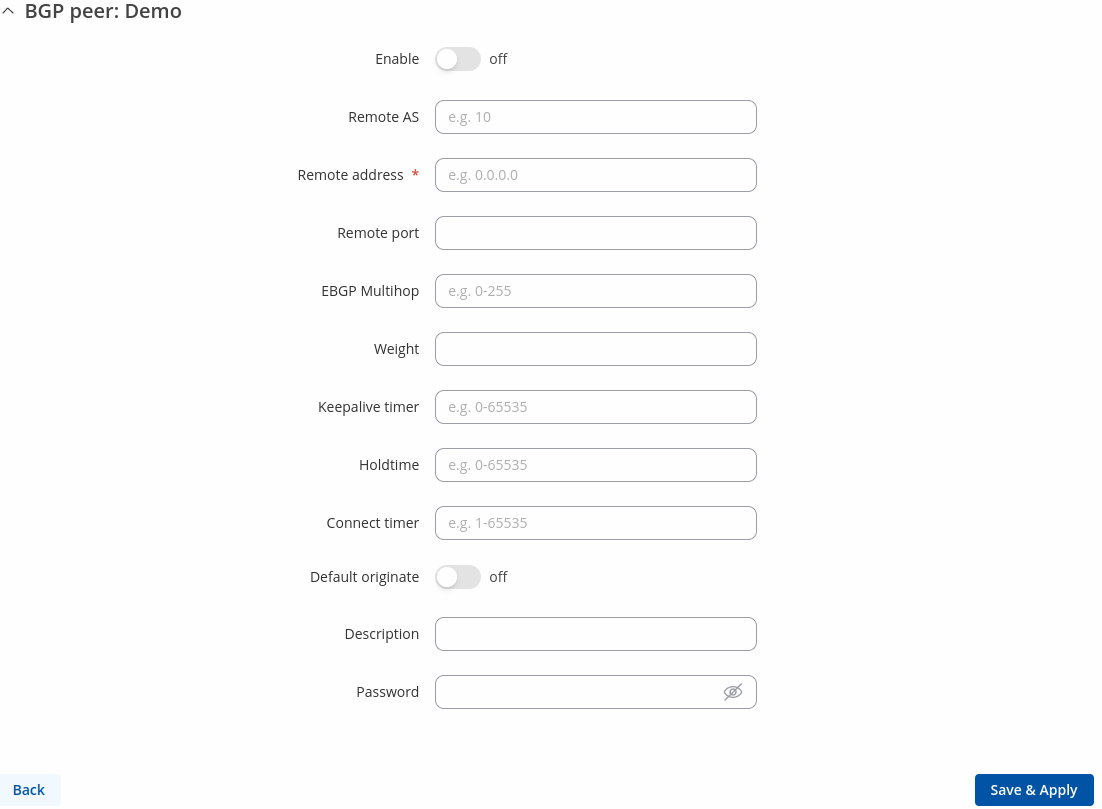
You will be redirected to general peer settings:
| Field | Value | Description |
|---|---|---|
| Enable | off | on; default: off | Turns this BGP peer on or off. |
| Remote AS | integer [1..4294967295]; default: none | Remote autonomous system number of this remote BGP Neighbor. |
| Remote address | ip4; default: none | IPv4 address of this remote BGP Neighbor. This option is required. |
| Remote port | integer [0..65535]; default: none | Listening port number of the BGP Neighbor. |
| EBGP Multihop | integer; default: none | Time to Live value for packets associated with this remote BGP Neighbor. |
| Weight | integer [0..65535]; default: none | Specifies a default weight value for the neighbor’s routes. Higher weight is preferred. |
| Keepalive timer | integer [0..65535]; default: none | Frequency (in seconds) of keep alive messages. |
| Holdtime | integer [0..65535]; default: none | Max wait time (in seconds) for a response from this neighbor before considering the peer unreachable. |
| Connect timer | integer [1..65535]; default: none | Max time (in seconds) to make a connection to this peer. If a connection cannot be made in this time, connection to this peer is considered unsuccessful. |
| Default originate | off | on; default: off | Announces default routes to this peer. |
| Description | string; default: none | A custom description for this BGP peer. Used for easier management purposes only. |
| Password | string; default: none | Password for this BGP Neighbor. |
BGP Peer Groups
A BGP Peer Group is a collection of routers that use the BGP protocol to dynamically redistribute routes among peers (other routers). The figure below is an example of the BGP Peer Groups section, which is empty by default.
To create a new Peer Group, look to the Add New Instance section under BGP Peer Groups; type in a custom name for the BGP Peer Group and click the 'Add' button:
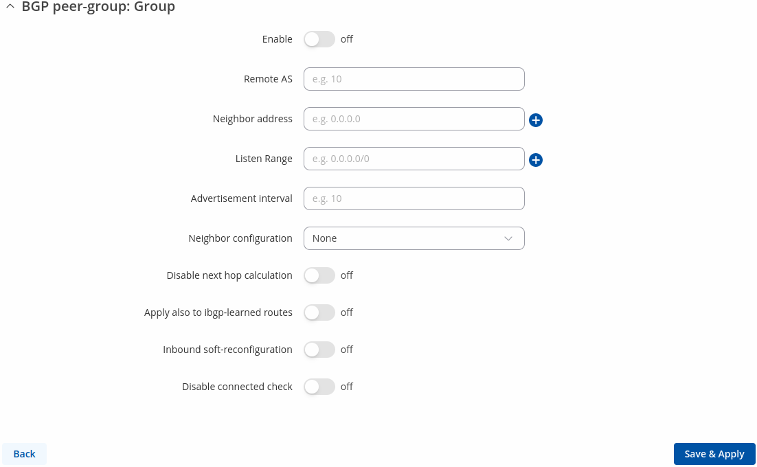
You will be redirected to general peer groups settings:
| Field | Value | Description |
|---|---|---|
| Enable | off | on; default: off | Turns the BGP Peer Group configuration on or off. |
| Remote AS | integer [1..65535]; default: none | Neighbour's remote AS. |
| Neighbor address | ip4; default: none | Neighbour's remote IPv4 address. |
| Listen Range | ip4 with mask; default: none | Accept connections from any peers in the specified prefix. |
| Advertisement interval | integer; default: none | Delay between updates for a neighbor session (in seconds). |
| Neighbor configuration | None | Route Reflector client | Route Server client; default: None | Defines the role of a BGP Neighbor.
|
| Disable next hop calculation | off | on; default: off | Turns next hop calculation for this BGP Peer Group on or off. |
| Apply also to ibgp-learned routes | off | on; default: off | When acting as a route reflector, applies to ibgp-learned routes as well. This field becomes visible when 'Disable next hop calculation' is turned on. |
| Inbound soft-reconfiguration | off | on; default: off | Turns inbound soft-reconfiguration for this Neighbor on or off. |
| Disable connected check | off | on; default: off | When turned on, Disable connected check enables a directly connected eBGP Neighbor to peer using a loopback address without adjusting the default TTL of 1. |
Route Map Filters
The Route Map Filters section is used to configure special filters that changes direction for BGP Peers. Below is an example of the Route Map Filters section which is empty by default. You can add a new filter by clicking the 'Add' button
An Route Map Filters configuration for BGP should look similar to this:
| Field | Value | Description |
|---|---|---|
| Peer | bgp peer; default: - | Applies the filter rule for the specified peer. |
| Route map | route map; default: - | Route map filter to apply. |
| Direction | Inbound | Outbound; default: Inbound | If direction is Inbound, the access list is applied to input routes. If direction is Outbound the access list is applied to advertised routes. |
| Enable | off | on; default: off | Turns an Route Map filter on or off. |
Access List Filters
The Access List Filters section is used to configure special filters that restrict or allow access to specified networks for BGP Peers. Below is an example of the Access List Filters section which is empty by default. You can add a new filter by clicking the 'Add' button
An Access List Filter configuration for BGP should look similar to this:
| Field | Value | Description |
|---|---|---|
| Peer | bgp peer; default: - | Applies the filter rule for the specified peer. |
| Action | Permit | Deny; default: Permit | When BGP traffic matches this rule, the device will take the action specified in this field, which is to either allow or block traffic. |
| Filter network | Any | custom; default: Any | Applies filter rule for this source network. |
| Direction | Inbound | Outbound; default: Inbound | If direction is Inbound, the access list is applied to input routes. If direction is Outbound the access list is applied to advertised routes. |
| Enable | off | on; default: off | Turns an Access filter on or off. |
Route Maps
A Route Maps allow you to configure a filtering criteria by defining a set of rules or match statements with a permit or deny condition. It includes a series of match statements to determine if a route matches the criteria defined in the statement and then apply the permit or deny rule accordingly.
To create a new Route Maps, look to the Add New Instance section under Route Maps; type in a custom name for the Route Map and click the 'Add' button:
You will be redirected to general route maps settings:
| Field | Value | Description |
|---|---|---|
| Enable | off | on; default: off | Turns the Route Maps configuration on or off. |
| Action | Permit | Deny; default: Permit | IPv4 address of this remote BGP Neighbor. |
| Local preference | integer [0..4294967295]; default: none | Used to determine best route towards a certain destination. |
| Metric | ip4 with mask; default: none | Sets a metric value for determining the preferred path into an AS. |
RIP
The Routing Information Protocol (RIP) is one of the oldest distance-vector routing protocols which employ the hop count as a routing metric. RIP prevents routing loops by implementing a limit on the number of hops allowed in a path from source to destination. The maximum number of hops allowed for RIP is 15, which limits the size of networks that RIP can support. A hop count of 16 is considered an infinite distance and the route is considered unreachable. RIP implements the split horizon, route poisoning and holddown mechanisms to prevent incorrect routing information from being propagated.
General Settings
The General Settings section is used to configure some of the main operating parameters of the RIP protocol. Below is an example of the RIP General Settings section.
| Field | Value | Description |
|---|---|---|
| Enable | off | on; default: off | Turns RIP Protocol usage on or off. |
| Enable vty | off | on; default: off | Turns vty access on or off. |
| Import config | - (interactive button) | Upload a external RIP configuration. |
| Version | 2 | 1; default: 2 | Specifies the used version of the RIP protocol. |
| Neighbor | rip neighbor; default: none | Defines a RIP Neighbor(s). |
RIP Interfaces
The RIP Interfaces section is used to define which existing network interfaces can participate in RIP communication. Below is an example of the RIP Interfaces section which is empty by default.
To create a new RIP Interface, look to the Add New Interface section; enter a custom name and click the 'Add' button:
RIP Interface configuration should look similar to this:
| Field | Value | Description |
|---|---|---|
| Interface | network interface; default: loopback | Network interface that will be used with the RIP protocol. |
| Passive interface | off | on; default: off | Sets the specified interface to passive mode. On passive mode interface, all receiving packets are processed as normal and ripd does not send either multicast or unicast RIP packets. |
| Enable | off | on; default: off | Turns a RIP Interface on or off. |
| Delete | - (interactive button) | Deletes RIP inerfaces instance. |
Access list filters
The Access List Filters section is used to configure special filters that restrict or allow access to specified networks for RIP Neighbors. Below is an example of the Access List Filters section which is empty by default.
To add a new filter, look to the Add New Instance section; enter a custom name and select RIP interface then click the 'Add' button:
An Access List Filter configuration for RIP should look similar to this:
| Field | Value | Description |
|---|---|---|
| Name | string on; default: none | A custom name for a filter. Used for easier management purposes only. |
| Enable | off | on; default: off | Turns an Access filter on or off. |
| RIP interface | rip interface; default: none | Specifies the RIP interface to which the filter will apply to. |
| Action | Permit | Deny; default: Permit | When RIP traffic matches this rule, the device will take the action specified in this field, which is to either allow or block traffic. |
| Network | ip/netmask | Any; default: Any | Matches traffic destined or originating from (depends on 'Direction' selection) to the network specified in this field. |
| Direction | Inbound | Outbound; default: Inbound | Matches network traffic direction, which can either be traffic destined to this device (Inbound) or traffic originating from this device (Outbound). |
OSPF
Open Shortest Path First (OSPF) is a routing protocol for Internet Protocol (IP) networks. It uses a link state routing (LSR) algorithm and falls into the group of interior gateway protocols (IGPs), operating within a single autonomous system (AS). It is defined as OSPF Version 2 in RFC 2328 for IPv4.
General Settings
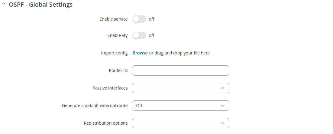
The General Settings section is used to configure some of the main operating parameters of the OSPF protocol. Below is an example of the OSPF General Settings section.
| Field | Value | Description |
|---|---|---|
| Enable | off | on; default: off | Turns OSPF Protocol usage on or off. |
| Enable vty | off | on; default: off | Turns vty access on or off. |
| Import | - (interactive) | Uploads a external OSPF configuration. |
| Router ID | 32-bit integer; default: none | Sets the router-ID in the OSPF network. |
| Passive interfaces | network interface(s); default: none | Network interfaces that should be considered as passive. OSPF hello packets are not sent on these interfaces. |
| Generate a default external route | off | default | always; default: off | Defines the behavior for advertising a default route over OSPF. Possible values are:
|
| Redistribution options | Connected routes | Kernel | NHRP | BGP | OSPF | RIP | EIGRP | Static; default: none | Distributes selected routes. Route redistribution is a process that allows a network to use a routing protocol to dynamically route traffic based on information learned from a separate routing protocol. |
OSPF Interface
The OSPF Interfaces section is used to define which existing network interfaces can participate in OSPF communication. Below is an example of the OSPF Interfaces section which is empty by default. To create a new OSPF Interface, simply click the 'Add' button:
OSPF Interface configuration should look similar to this:
| Field | Value | Description |
|---|---|---|
| Interface | network interface; default: loopback | Network interface that will be used with the OSPF protocol. |
| Enable | off | on; default: off | Turns an OSPF Interface on or off. |
To see more settings for an OSPF interface, click the 'Edit' button next to it:
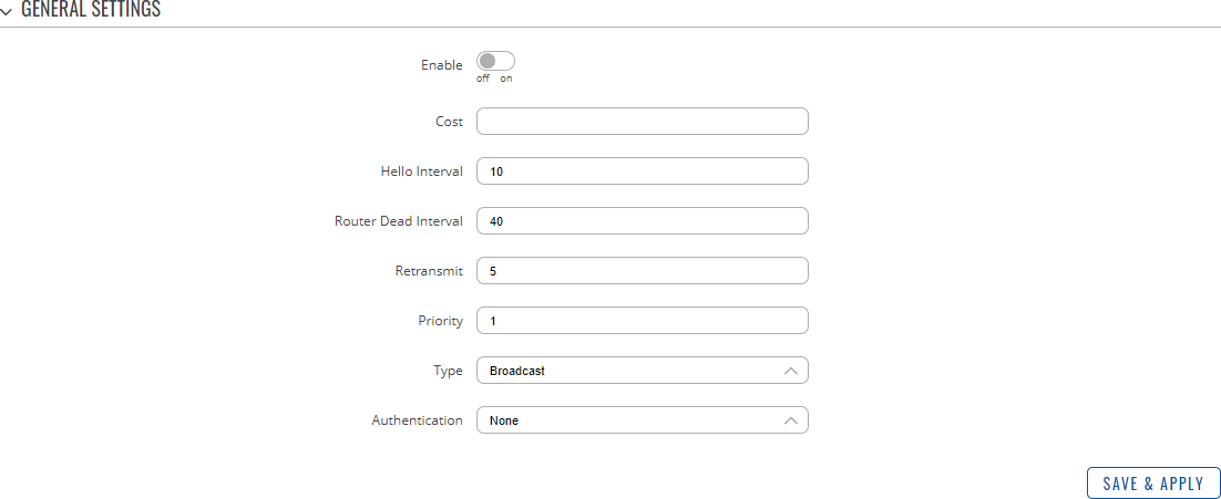
You should directed to a window such as this:
| Field | Value | Description |
|---|---|---|
| Enable | off | on; default: off | Turns the OSPF area on or off. |
| Cost | integer [1..65535]; default: none | The cost value is set to router-LSA’s metric field and used for SPF calculation. |
| Hello Interval | integer [1..65535]; default: 10 | Frequency (in seconds) at which a "Hello" packet is sent out on the specified interface. |
| Router Dead Interval | integer [1..65535]; default: 40 | This value must be the same for all routers attached to a common OSPF network. |
| Retransmit | integer [0..65535]; default: 5 | Used in Database Description and Link State Request packet re-transmission. |
| Priority | integer [0..255]; default: 1 | OSPF router priority. The router with the highest priority will be more eligible to become the "Designated Router". Setting the value to 0, makes the router ineligible to become a "Designated Router." |
| Type | Broadcast | Non-Broadcast | Point-to-point | Point-to-Multipoint; default: Broadcast | OSPF interface configuration type. |
| Authentication | None | Password | MD5 HMAC; default: None | Specifies the Authentication method. |
OSPF Neighbors
The OSPF Neighbors section can be used to configure other users ("neighbors") of the same OSPF network statically.
| Field | Value | Description |
|---|---|---|
| Enable | off | on; default: off | Turns this OSPF neighbor configuration on or off. |
| Neighbor | ip4; default: none | IP address of the OSPF neighbor. |
| Neighbor Priority | integer [1..255]; default: none | Priority of this neighbor |
| Polling interval | integer [1..65535]; default: none | Check for dead neighbor interval (in seconds). |
OSPF Area
An OSPF Area is a collection of OSPF Networks that can serve each other. Below is an example of the OSPF Area section which is empty by default.
To add a new OSPF Area, look to the Add New Area section; enter a custom name and click the 'Add' button.
The newly added new Area will appear in the OSPF Area list.
| Field | Value | Description |
|---|---|---|
| Name | string on; default: none | A custom name for an OSPF Area. Used for easier management purposes only. |
| Area | 32-bit integer; default: none | OSPF Area ID. OSPF Networks that are meant to communicate with each other should belong to the same Area (have the Area ID). |
| STUB | off | on; default: off | A stub area is an area in which advertisements of external routes are not allowed, reducing the size of the database. |
| Enable | off | on; default: off | Turns an OSPF Area on or off. |
OSPF Networks
The OSPF Network section is used to add networks to OSPF areas that can later be shared (provide access to) with other OSPF routers.
Below is an example of the OSPF Area section which is empty by default.
To add a new OSPF Network, look to the Add New Network section; enter a custom name and click the 'Add' button.
Your new network will appear in the OSPF Networks list
| Field | Value | Description |
|---|---|---|
| Name | string on; default: none | A custom name for an OSPF Area. Used for easier management purposes only. |
| Network | ip/netmask; default: none | IP address/netmask of a network. OSPF Network locations are shared with other OSPF routers. |
| Area | OSPF area; default: none | ID of an OSPF Area (to which this network should belong to). |
| Enable | off | on; default: off | Turns the usage of this network (in OSPF) on or off. |
EIGRP
Enhanced Interior Gateway Routing Protocol (EIGRP) is an advanced distance-vector routing protocol that is used on a computer network for automating routing decisions and configuration.
General
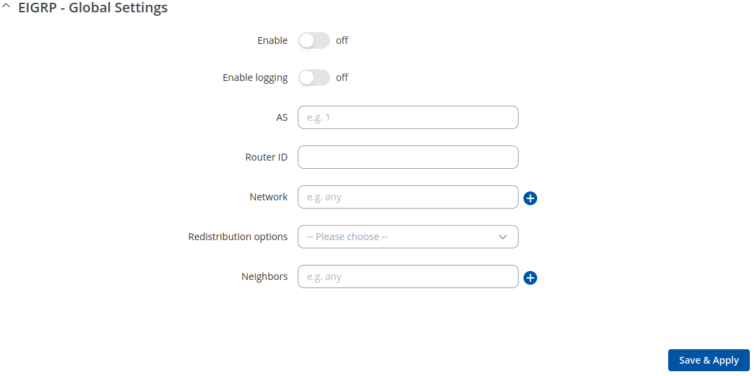
The General Settings section is used to configure some of the main operating parameters of the EIGRP protocol. Below is an example of the EIGRP General Settings section.
| Field | Value | Description |
|---|---|---|
| Enable | off | on; default: off | Turns EIGRP protocol usage on or off. |
| Enable logging | off | on; default: off | Turns logging of EIGRP traffic on or off. |
| AS | integer [1..65535]; default: none | EIGRP Autonomous System (AS) number. It is an identifier that represents a routing domain; EIGRP routers can exchange routes within the same Autonomous System. |
| Router ID | ip4; default: none | The router ID is used by EIGRP to identify the routing device from which a packet originated. Default router ID value is selected as the largest IP Address of the interface. |
| Network | ip/netmask; default: none | Adds an announcement network(s). Routes to these networks will be shared over EIGRP. |
| Redistribution options | Connected routes | Kernel added routes | NHRP routes | OSPF routes | Static routes | custom; default: none | Distributes selected routes. Route redistribution is a process that allows a network to use a routing protocol to dynamically route traffic based on information learned from a separate routing protocol. |
| Neighbors | ip4; default: none | Defines the EIGRP Neighbors (based on their IP addresses) that this device is meant to associate with. |
NHRP
Next Hop Resolution Protocol (NHRP) is a protocol or method that can be used so that a computer sending data to another computer can learn the most direct route (the fewest number of hops) to the receiving computer.
General Settings
The General Settings section is used to turn NHRP protocol usage on or off. Below is an example of the NHRP General Settings section.
| Field | Value | Description |
|---|---|---|
| Enable service | off | on; default: off | Turns NHRP protocol usage on or off. |
| Enable logging | off | on; default: off | Turns NHRP traffic logging on or off. |
Interfaces
The Interfaces section is used to define which existing network interfaces can participate in NHRP communication. Below is an example of the NHRP Interfaces section which is empty by default.
To create a new NHRP Interface, look to the Add New Interface section; enter a custom name and click the 'Add' button.
The newly added NHRP interface will appear in the Interfaces list and should look similar to this:
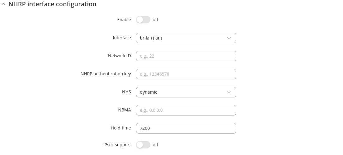
To see more settings for an NHRP Interface, click the 'Edit' button next to it. You will be redirected to a window that looks similar to this:
| Field | Value | Description |
|---|---|---|
| Enabled | off | on; default: off | Turns the NHRP Interface on or off. |
| Interface | network interface; default: br-lan | Network interface associated with this NHRP Interface. |
| Network ID | 32-bit integer; default: none | A numerical identifier for this NHRP Interface. |
| NHRP authentication key | string; default: none | A password used in NHRP authentication. |
| NHS | dynamic | custom(ip4); default: dynamic | IP address of a Next-Hop server. |
| NBMA | ip4; default: none | Non-Broadcast Multi-Access (NBMA) network IP address. |
| Hold-time | integer; default: 7200 | Specifies the holding time (in seconds) for NHRP Registration Requests and Resolution Replies sent from this interface or shortcut-target. |
| IPsec support | off | on; default: off | Turns usage of NHRP over IPsec for this Interface on or off. |
| IPsec instance | string; default: none | Specifies which existing IPsec instance should be associated with this NHRP Interface. This field becomes visible only when IPsec support is set to 'on'. |
NHRP Mappings Configuration
The NHRP Mappings Configuration section is used to configure (map) associations between NHRP router IP address and NBMAs. Below is an example of the NHRP Mappings Configuration section which is empty by default. To add a new configuration, simply click the 'Add' button:
The newly added configuration should appear in the NHRP Mappings Configuration list and look similar to this:
| Field | Value | Description |
|---|---|---|
| IP Address | ip4; default: none | Network ID of another NHRP router. |
| NBMA | ip4; default: none | IP address of a Next-Hop server. |
| Enabled | off | on; default: off | Turns this mapping configuration on or off. |
NHRP NHS Configuration
The NHRP uses next hop servers (NHS) to register. Below is an example of the NHRP NHS Configuration section which is empty by default. To add a new configuration, simply click the 'Add' button:
The newly added configuration should appear in the NHRP NHS Configuration list and look similar to this:
| Field | Value | Description |
|---|---|---|
| NHS IP Address | ip4; default: none | Static Next Hop Server IP address. |
| NBMA | ip4; default: none | Non-Broadcast Multi-Access(NBMA) network IP address of this NHS. |
| Enabled | off | on; default: off | Turns NHFRP NHS configuration on or off. |


