TRB255 RS485: Difference between revisions
No edit summary |
mNo edit summary |
||
| (2 intermediate revisions by 2 users not shown) | |||
| Line 1: | Line 1: | ||
{{Template: Networking_rutos_manual_rs485 | {{Template: Networking_rutos_manual_rs485 | ||
<!------------------------DEVICE-----------------------> | <!------------------------DEVICE-----------------------> | ||
| name | | name = TRB255 | ||
| series = TRB2 | | series = TRB2 | ||
<!----------------------SEPARATORS---------------------> | |||
| baud_rate = 115200 <!-- Default baud rate --> | |||
| baud_rates = 300 {{!}} 600 {{!}} 1200 {{!}} 2400 {{!}} 4800 {{!}} 9600 {{!}} 14400 {{!}} 19200 {{!}} 38400 {{!}} 56000 {{!}} 57600 {{!}} 115200 {{!}} 230400 {{!}} 460800 {{!}} 921600 {{!}} 1000000 {{!}} 3000000 <!-- All baud rate values--> | |||
| data_bit = 7 <!-- Default data bits --> | |||
| data_bits = 7 {{!}} 8 <!-- All data bits values --> | |||
| modem = 1 | |||
}} | }} | ||
Latest revision as of 17:03, 4 February 2022
Main Page > EOL Products > TRB255 > TRB255 Manual > TRB255 WebUI > TRB255 Services section > TRB255 RS485The information in this page is updated in accordance with firmware version TRB2_R_00.07.10.2.
RS485 service was moved to Serial Utilities page from FW version TRB2_R_00.07.03.
Summary
The RS485 page is used to configure the operating parameter of RS485 serial connector.
This manual page provides an overview of the RS485 page in TRB255 devices.
General information
Maximum data rate vs. transmission line length
The RS485 standard can be used for network lengths up to 1200 meters, but the maximum usable data rate decreases as the transmission length increases. A device operating at the maximum data transfer rate (10 Mbps) is limited to a transmission length of about 12 meters, while a distance up to 1200 meters can be achieved at 100 Kbps. A rough relation between maximum transmission length and data rate can be calculated using this approximation:
Where:
- Lmax - maximum cable length in meters.
- DR - maximum data rate in bits per second.
Twisted pair is the preferred cable type for RS485 networks. Twisted pair cables pick up noise and other electromagnetically induced voltages as common mode signals, which are rejected by the differential receivers.
2-Wire and 4-Wire Networks
Below is an example of a 4-wire network electrical connection. There are 3 devices shown in the example. One of the devices is the "master" and other two are "slaves". Termination resistors (120 Ω each) are placed at each cable end. Four-wire networks consists of one master with its transmitter connected to each of the slaves' receivers on one twisted pair. The slave transmitters are all connected to the master receiver on a second twisted pair:
Example 2-wire network electrical connection: to enable a 2-wire RS485 configuration you need to connect D_P to R_P and D_N to R_N on the device’s RS485 socket. Termination resistors are placed at each cable end (120 Ω each):
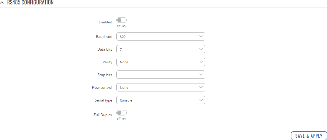
RS485 Configuration
The RS485 Configuration section is used to set up the main operating parameters and the serial type of the RS485 connector.
| Field | Value | Description |
|---|---|---|
| Enabled | off | on; default: off | Turns the RS485 service on or off. |
| Baud rate | 300 | 600 | 1200 | 2400 | 4800 | 9600 | 14400 | 19200 | 38400 | 56000 | 57600 | 115200 | 230400 | 460800 | 921600 | 1000000 | 3000000; default: 115200 | Data rate for serial data transmission (in bits per second (bps)). |
| Data bits | 5 | 6 | 7 | 8; default: 7 | Number of data bits for each character. |
| Parity | None | Odd | Even; default: None | In serial transmission, parity is a method of detecting errors. An extra data bit is sent with each data character, arranged so that the number of 1 bits in each character, including the parity bit, is always odd or always even. If a byte is received with the wrong number of 1s, then it must have been corrupted. However, an even number of errors can pass the parity check.
|
| Stop bits | 1 | 2; default: 1 | Stop bits sent at the end of every character allow the receiving signal hardware to detect the end of a character and to resynchronise with the character stream. Electronic devices usually use one stop bit. Two stop bits are required if slow electromechanical devices are used. |
| Flow control | None | RTS/CTS | Xon/Xoff; default: None | In many circumstances a transmitter might be able to send data faster than the receiver is able to process it. To cope with this, serial lines often incorporate a "handshaking" method, usually distinguished between hardware and software handshaking.
|
| Serial type | Console | Over IP | Modem | Modbus gateway; default: Console | Specifies the serial connection type. Look to the sections below for information on different RS485 serial type options. |
| Full Duplex | off | on; default: off | Turns RS485 Full Duplex mode on or off. |
Console
Console mode requires no further configuration than the settings above and is used as a direct-access method to the device's shell interface. For this purpose you may want use such applications as PuTTY on Windows and microcom, minicom, picocom or similar applications on Linux.
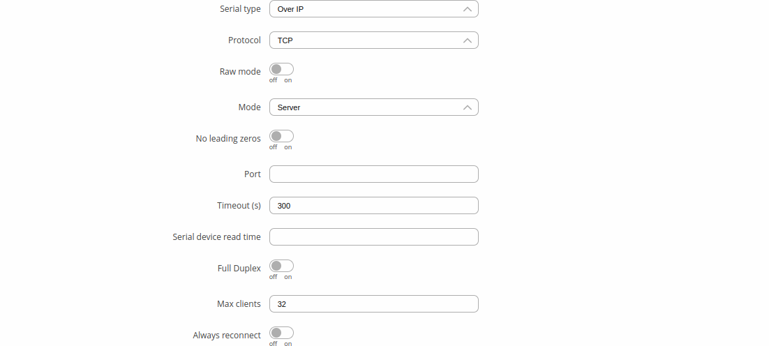
Over IP
The Over IP serial type is used to manage serial connections over a TCP/IP network.
| Field | Value | Description |
|---|---|---|
| Protocol | TCP | UDP; default: TCP | Protocol used in the communication process. |
| Raw mode | off | on; default; default: off | When enabled, all data will be transmitted transparently. |
| Mode | Server | Client | Bidirect; default: Server | This device's role in the connection:
|
| No leading zeros | off | on; default: off | When checked, indicates that the first hex zeros should be skipped. |
| Server settings: Port | integer [0..65535]; default: none | Internal port number used to listen for incoming connections. |
| Server settings | TCP: Timeout (s) | integer [0..32767]; default: 300 | Specifies an inactivity time limit (in seconds) after which an inactive clients is disconnected. |
| Bidirect: Output | Configurable Input/Output (2) | Configurable Input/Output (3) | Configurable Input/Output (4); default: Configurable Input/Output (2) | Specifies which output to manage. |
| Bidirect: Output state | 0 | 1; default: 0 | Default output state value, when the application is started. |
| Server settings | UDP: Number of clients | 1-10; default: 1 | Specifies how many UDP clients will be supported simultaneously (predefined clients does not count towards this limit). |
| Server settings | UDP: Predefined client 1 address | ip4; default: none | Specifies IP address for predefined connection 1. |
| Server settings | UDP: Predefined port 1 | port; default: none | Specifies port number for predefined connection 1. |
| Server settings | UDP: Predefined client 2 address | ip4; default: none | Specifies IP address for predefined connection 2. |
| Server settings | UDP: Predefined port 2 | port; default: none | Specifies port number for predefined connection 2. |
| Client settings: Server Address | ip | host; default: none | IP address or hostname of the server that this client will connect to. |
| Client settings: Port | integer [0..65535]; default: none | Server's listening port number. |
| Client settings: Reconnect interval (s) | integer; default: none | Time period (in seconds) between reconnection attempts in case a connection fails. |
| Serial device read time | integer [0..1000]; default: none | Specifies custom read time for the serial device. |
| Full Duplex | 0 | 1; default: 0 | Enables RS485 Full-Duplex. |
| Server settings | TCP: Max clients | integer [1..32]; default: 32 | Specifies how many clients are allowed to connect simultaneously. |
| TCP: Always reconnect | off | on; default: off | When enabled, a new TCP connection will be made after sending every data package. |
Modem
The Modem serial type is used to manage modem functionality which could be accessed using shell interface. For this purpose you may want use such applications with CR/LF (Carriage Return, Line Feed) capable applications like PuTTY on Windows and microcom, minicom, cutecom or similar applications on Linux.
| Field | Value | Description |
|---|---|---|
| Mode | Partial control | Full control; default: Partial control | Specifies modem control mode.
|
Modbus gateway
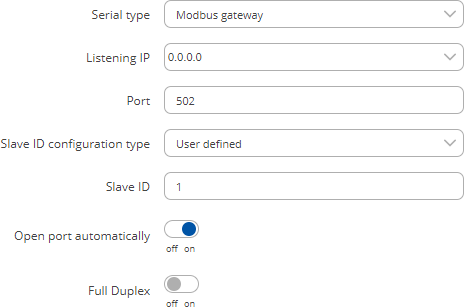
The Modbus gateway serial type allows redirecting TCP data coming to a specified port to an RTU specified by the Slave ID. The Slave ID can be specified by the user or be obtained directly from the Modbus header.
| Field | Value | Description |
|---|---|---|
| Listening IP | ip; default: 0.0.0.0 | IP address to listen for incoming connections. The default value (0.0.0.0) means that this device will listen for incoming connections on any interface or IP address. |
| Port | integer [0..65535]; default: 502 | Port number to listen for incoming connections. |
| Slave ID configuration type | User defined | Obtained from TCP; default: User defined |
Specifies whether slave IDs are user defined or automatically obtained from TCP. |
| Slave ID | Permitted slave IDs | integer | range of integers; default: 1 or 1-247 |
Specifies the slave ID of range of permitted slave IDs. The way this field is named and its function depends on the value of the Slave ID configuration field. A range of IDs can be specified by placing a hyphen (-) between two integer numbers. For example, if you permit slave IDs in the range of 10 to 20, you would specify it as: 10-20 You can also specify multiple values that are not connected in a range using commas (,). For example, to specify 6, 50 and 100 as permitted slave IDs, you would have to use: 6,50,100 |
| Open port automatically | off | on; default: on | Automatically adds a traffic rule in the firewall configuration to open the required port for serial communication. Caution: use with care if listening IP is left as the default value (0.0.0.0). Leaving it as such will leave the device open for remote connections on the specified port. |
| Full duplex | off | on; default: off | Turns RS485 full duplex on or off. |
IP Filter
The IP Filter section is used for configuring which network is allowed to communicate with the device. You may add a new instance by selecting the Interface and pressing Add.
Then enter the IP address and save.


