DMVPN with IPsec Phase 3: Difference between revisions
mNo edit summary |
No edit summary |
||
| Line 33: | Line 33: | ||
- Set Pre-shared key (we used simple 123456 for this example) | - Set Pre-shared key (we used simple 123456 for this example) | ||
<br>[[File:DMVP_HUB_phase3_example1.png]] | <br>[[File:DMVP_HUB_phase3_example1.png|border|class=tlt-border]] | ||
---- | ---- | ||
<b>Step 2</b>: configure DMVPN Phase 1 parameters: | <b>Step 2</b>: configure DMVPN Phase 1 parameters: | ||
| Line 43: | Line 43: | ||
- DH group - MODP1024 | - DH group - MODP1024 | ||
<br>[[File:DMVP HUB phase3 example2.png]] | <br>[[File:DMVP HUB phase3 example2.png|border|class=tlt-border]] | ||
---- | ---- | ||
<b>Step 3</b>: configure DMVPN Phase 2 parameters: | <b>Step 3</b>: configure DMVPN Phase 2 parameters: | ||
| Line 53: | Line 53: | ||
- PFS group -MODP768 | - PFS group -MODP768 | ||
<br>[[File:DMVPN HUB Phase3 example3.png]] | <br>[[File:DMVPN HUB Phase3 example3.png|border|class=tlt-border]] | ||
---- | ---- | ||
<b>Step 4</b>: configure DMVPN NHRP parameters: | <b>Step 4</b>: configure DMVPN NHRP parameters: | ||
<br>[[File:DMVPN HUB Phase3 example4.png]] | <br>[[File:DMVPN HUB Phase3 example4.png|border|class=tlt-border]] | ||
---- | ---- | ||
<b>Step 5</b>: save changes | <b>Step 5</b>: save changes | ||
| Line 73: | Line 73: | ||
- Set announcement network(s). Routes to these networks will be shared over BGP. We used 192.168.1.0/24 | - Set announcement network(s). Routes to these networks will be shared over BGP. We used 192.168.1.0/24 | ||
<br>[[File:DMVPN HUB Phase3 example5.png]] | <br>[[File:DMVPN HUB Phase3 example5.png|border|class=tlt-border]] | ||
---- | ---- | ||
| Line 81: | Line 81: | ||
- Add Neighbor address (We used 10.0.0.1 and 10.0.0.2) | - Add Neighbor address (We used 10.0.0.1 and 10.0.0.2) | ||
<br>[[File:DMVPN HUB Phase3 example6.png]] | <br>[[File:DMVPN HUB Phase3 example6.png|border|class=tlt-border]] | ||
---- | ---- | ||
| Line 99: | Line 99: | ||
- Set Remote address as 10.0.0.2 | - Set Remote address as 10.0.0.2 | ||
<br>[[File:DMVPN HUB Phase3 example7.png]] | <br>[[File:DMVPN HUB Phase3 example7.png|border|class=tlt-border]] | ||
---- | ---- | ||
[[File:DMVPN HUB Phase3 example8.png]] | [[File:DMVPN HUB Phase3 example8.png|border|class=tlt-border]] | ||
---- | ---- | ||
| Line 123: | Line 123: | ||
- Set Local identifier, Remote identifier as %any and input same Pre-shared key | - Set Local identifier, Remote identifier as %any and input same Pre-shared key | ||
<br>[[File:DMVPN HUB Phase3 spoke1 example1.png]] | <br>[[File:DMVPN HUB Phase3 spoke1 example1.png|border|class=tlt-border]] | ||
---- | ---- | ||
| Line 135: | Line 135: | ||
- Select DH group MODP1024 | - Select DH group MODP1024 | ||
<br>[[File:DMVPN HUB Phase3 spoke example2.png]] | <br>[[File:DMVPN HUB Phase3 spoke example2.png|border|class=tlt-border]] | ||
---- | ---- | ||
| Line 147: | Line 147: | ||
- Select PFS group MODP768 | - Select PFS group MODP768 | ||
<br>[[File:DMVPN HUB Phase3 spoke example3.png]] | <br>[[File:DMVPN HUB Phase3 spoke example3.png|border|class=tlt-border]] | ||
---- | ---- | ||
| Line 155: | Line 155: | ||
- Leave everything by default | - Leave everything by default | ||
<br>[[File:DMVPN HUB Phase3 spoke example4.png]] | <br>[[File:DMVPN HUB Phase3 spoke example4.png|border|class=tlt-border]] | ||
---- | ---- | ||
<b>Step 5</b>: save changes | <b>Step 5</b>: save changes | ||
| Line 171: | Line 171: | ||
- Set Network to 192.168.10.0/24 | - Set Network to 192.168.10.0/24 | ||
<br>[[File:DMVPN HUB Phase3 spoke example5.png]] | <br>[[File:DMVPN HUB Phase3 spoke example5.png|border|class=tlt-border]] | ||
---- | ---- | ||
| Line 181: | Line 181: | ||
- Set Remote address to 10.0.0.254 | - Set Remote address to 10.0.0.254 | ||
<br>[[File:DMVPN HUB Phase3 spoke example6.png]] | <br>[[File:DMVPN HUB Phase3 spoke example6.png|border|class=tlt-border]] | ||
===Spoke 2 configuration: DMVPN=== | ===Spoke 2 configuration: DMVPN=== | ||
| Line 199: | Line 199: | ||
- Set GRE MTU to 1476 | - Set GRE MTU to 1476 | ||
<br>[[File:DMVPN HUB Phase3 spoke2 example1.png]] | <br>[[File:DMVPN HUB Phase3 spoke2 example1.png|border|class=tlt-border]] | ||
---- | ---- | ||
| Line 211: | Line 211: | ||
- Select DH group MODP1024 | - Select DH group MODP1024 | ||
<br>[[File:DMVPN HUB Phase3 spoke2 example2.png]] | <br>[[File:DMVPN HUB Phase3 spoke2 example2.png|border|class=tlt-border]] | ||
---- | ---- | ||
<b>Step 3</b>: configure DMVPN Phase 2 parameters: | <b>Step 3</b>: configure DMVPN Phase 2 parameters: | ||
| Line 221: | Line 221: | ||
- Select PFS group MODP768 | - Select PFS group MODP768 | ||
<br>[[File:DMVPN HUB Phase3 spoke2 example3.png]] | <br>[[File:DMVPN HUB Phase3 spoke2 example3.png|border|class=tlt-border]] | ||
---- | ---- | ||
| Line 227: | Line 227: | ||
<b>Step 4</b>: configure DMVPN NHRP parameters: | <b>Step 4</b>: configure DMVPN NHRP parameters: | ||
<br>[[File:DMVPN HUB Phase3 spoke2 example4.png]] | <br>[[File:DMVPN HUB Phase3 spoke2 example4.png|border|class=tlt-border]] | ||
---- | ---- | ||
<b>Step 5</b>: save changes | <b>Step 5</b>: save changes | ||
| Line 243: | Line 243: | ||
- Set Network to 192.168.20.0/24 | - Set Network to 192.168.20.0/24 | ||
<br>[[File:DMVPN HUB Phase3 spoke2 example5.png]] | <br>[[File:DMVPN HUB Phase3 spoke2 example5.png|border|class=tlt-border]] | ||
---- | ---- | ||
| Line 253: | Line 253: | ||
- Set Remote address to 10.0.0.254 | - Set Remote address to 10.0.0.254 | ||
<br>[[File:DMVPN HUB Phase3 spoke2 example6.png]] | <br>[[File:DMVPN HUB Phase3 spoke2 example6.png|border|class=tlt-border]] | ||
===Important Note=== | ===Important Note=== | ||
| Line 260: | Line 260: | ||
---- | ---- | ||
[[File:DMVPN HUB Phase3 example Firewall.png]] | [[File:DMVPN HUB Phase3 example Firewall.png|border|class=tlt-border]] | ||
---- | ---- | ||
| Line 267: | Line 267: | ||
---- | ---- | ||
[[File:DMVPN HUB Phase3 example Behind NAT.png]] | [[File:DMVPN HUB Phase3 example Behind NAT.png|border|class=tlt-border]] | ||
Revision as of 13:47, 20 December 2022
Main Page > General Information > Configuration Examples > VPN > DMVPN with IPsec Phase 3Introduction
This article contains instructions on how to configure DMVPN Phase 3 between a "Hub" and two "Spokes" using Teltonika devices.
Prerequisites and overview
You will need:
- 2 Teltonika Routers for "Spokes" and one for "Hub"
- A PC to configure the routers
- HUB must have a Public IP address
HUB configuration
This section contains information on how to configure DMVPN HUB. Firstly, we'll configure the DMVPN instance to make the connection possible. Then we'll set the Border Gateway Protocol (BGP) parameters as our dynamic routing solution.
Note: at the moment, BGP is the only stable dynamic routing solution that can work with DMVPNs.
HUB configuration: DMVPN
Navigate to the Services → VPN → DMVPN page and follow the instructions provided below.
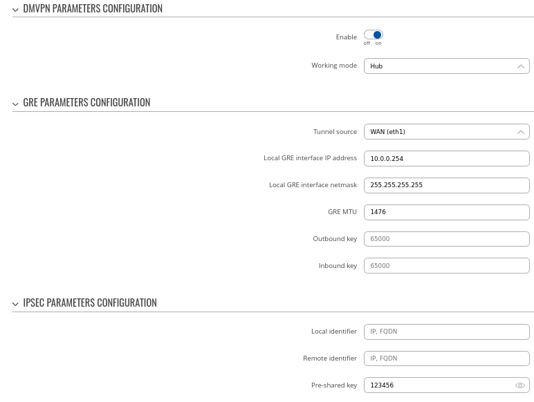
Step 1: create a new DMVPN instance:
- Select your HUB interface in the Tunnel source field
- Set Local GRE interface IP address (for example, 10.0.0.254)
- Set GRE MTU value to 1476
- Set Pre-shared key (we used simple 123456 for this example)
Step 2: configure DMVPN Phase 1 parameters:
- Encryption algorithm - AES 128
- Authentication SHA1
- DH group - MODP1024
Step 3: configure DMVPN Phase 2 parameters:
- Encryption algorithm - 3DES
- Hash algorithm - MD5
- PFS group -MODP768
Step 4: configure DMVPN NHRP parameters:
Step 5: save changes
Hub configuration: BGP
Navigate to the Network → Routing → Dynamic Routes → BGP Protocol page and follow the instructions provided below.
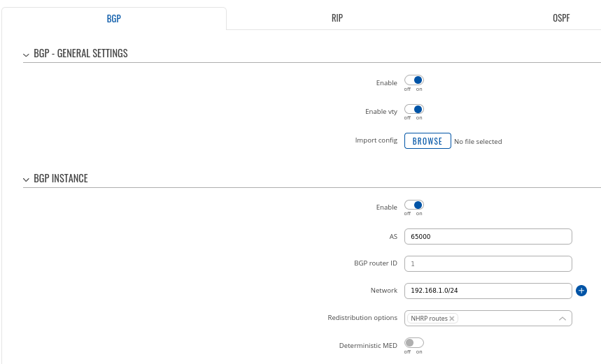
Step 1: enable BGP and configure General section:
- Enable vty
- Set AS to 65000
- Set announcement network(s). Routes to these networks will be shared over BGP. We used 192.168.1.0/24
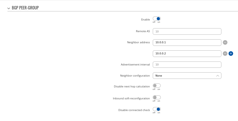
Step 2: Create BGP Peer Group:
- Add Neighbor address (We used 10.0.0.1 and 10.0.0.2)
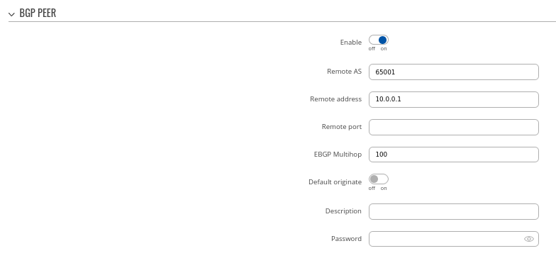
Step 3: Add two BGP peers for each spoke:
Peer 1.
- Set Remote AS to 65001
- Set Remote address as 10.0.0.1
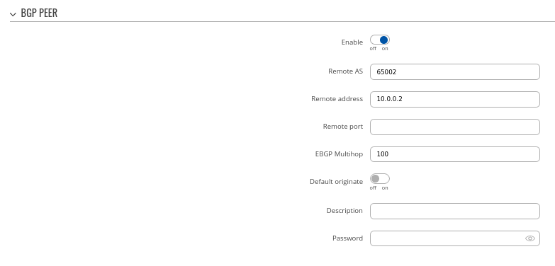
Peer 2.
- Set Remote AS to 65002
- Set Remote address as 10.0.0.2
Spoke 1 configuration: DMVPN
Navigate to the Services → VPN → DMVPN page and follow the instructions provided below.
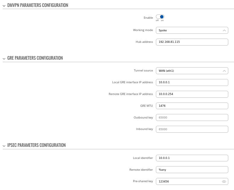
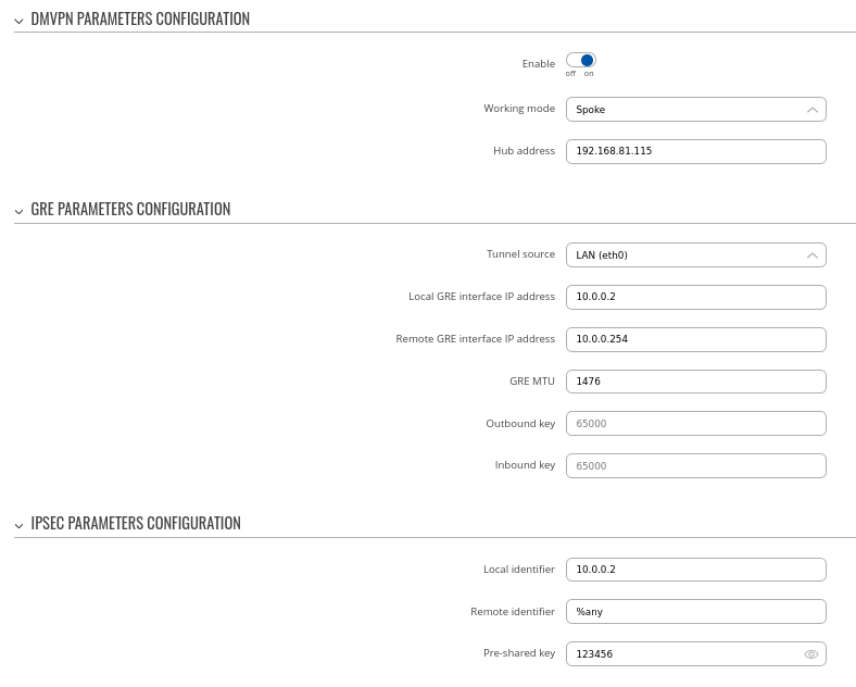
Step 1: create a new DMVPN instance:
- Add HUB address
- Select Tunnel source
- Add Local GRE interface IP address
- Add Remote GRE interface IP address
- Set GRE MTU
- Set Local identifier, Remote identifier as %any and input same Pre-shared key
Step 2: configure DMVPN Phase 1 parameters:
- Select Encryption algorithm - AES 128
- Select Authentication SHA1
- Select DH group MODP1024
Step 3: configure DMVPN Phase 2 parameters:
- Select Encryption algorithm 3DES
- Select Hash algorithm MD5
- Select PFS group MODP768
Step 4: configure DMVPN NHRP parameters:
- Leave everything by default
Step 5: save changes
Spoke 1 configuration: BGP
Navigate to the Network → Routing → Dynamic Routes → BGP Protocol page and follow the instructions provided below.
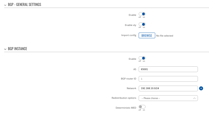
Step 1: enable BGP and configure General section:
- Enable vty
- Set AS to 65001
- Set Network to 192.168.10.0/24
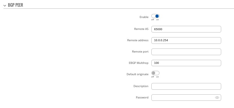
Step 2: Create BGP Peer:
- Set Remote AS to 65000
- Set Remote address to 10.0.0.254
Spoke 2 configuration: DMVPN
Navigate to the Services → VPN → DMVPN page and follow the instructions provided below.
Step 1: create a new DMVPN instance:
- Input your HUB address
- Select Tunnel source interface
- Set Local GRE interface address to 10.0.0.2
- Set Remote GRE interface IP address to 10.0.0.254
- Set GRE MTU to 1476
Step 2: configure DMVPN Phase 1 parameters:
- Select Encryption algorithm - AES 128
- Select Authentication SHA1
- Select DH group MODP1024
Step 3: configure DMVPN Phase 2 parameters:
- Select Encryption algorithm 3DES
- Select Hash algorithm MD5
- Select PFS group MODP768
Step 4: configure DMVPN NHRP parameters:
Step 5: save changes
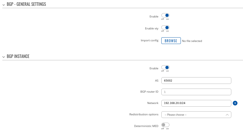
Spoke 2 configuration: BGP
Navigate to the Network → Routing → Dynamic Routes → BGP Protocol page and follow the instructions provided below.
Step 1: enable BGP and configure General section:
- Enable vty
- Set AS to 65002
- Set Network to 192.168.20.0/24
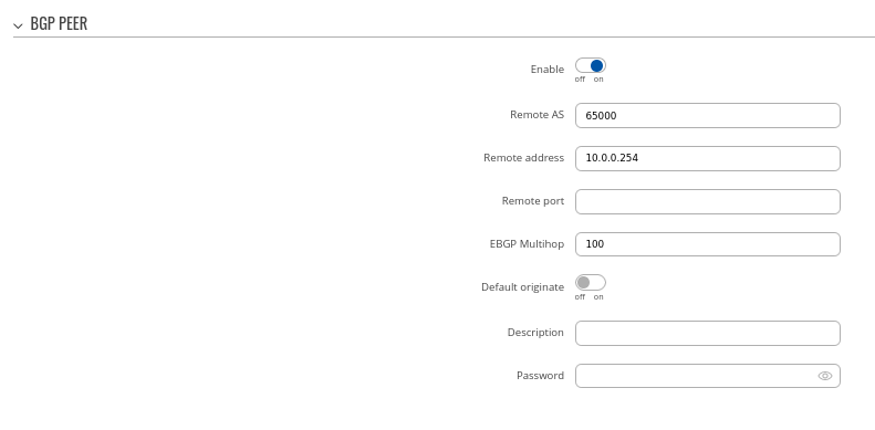
Step 2: Create BGP Peer:
- Set Remote AS to 65000
- Set Remote address to 10.0.0.254
Important Note
For HUB in Network > Firewall GRE zone change from REJECT to ACCEPT on FORWARD.
For setups behind NAT specify Local identifier in the Services → VPN → DMVPN → IPsec section

