Template:Networking device manual panels: Difference between revisions
No edit summary |
No edit summary |
||
| Line 2: | Line 2: | ||
{{Template: Networking_{{lc:{{{name}}}}}_manual_panels_front | {{Template: Networking_{{lc:{{{name}}}}}_manual_panels_front | ||
| | | file_front = {{{file_front}}} | ||
| | | size_front = {{{size_front}}} | ||
}} | }} | ||
{{Template: Networking_{{lc:{{{name}}}}}_manual_panels_back | {{Template: Networking_{{lc:{{{name}}}}}_manual_panels_back | ||
| | | file_back = {{{file_back}}} | ||
| | | size_back = {{{size_back}}} | ||
}} | }} | ||
---- | ---- | ||
Revision as of 12:54, 19 February 2019
This chapter provides a description of the components found on the front and back panels of a {{{name}}} router.
{{Template: Networking_{{{name}}}_manual_panels_front | file_front = {{{file_front}}} | size_front = {{{size_front}}} }}
{{Template: Networking_{{{name}}}_manual_panels_back | file_back = {{{file_back}}} | size_back = {{{size_back}}} }}
Template:Main aux antenna dependency
| SEVENTH SYMBOL | MAIN ANTENNA | AUX ANTENNA |
|---|---|---|
| A, H, J, K, L, M, P | 1 | 3 |
| 1, 3, 5, 7, 9, B, F | 3 | 1 |
| 0, 2, G | 3 | 1 |
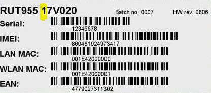
Below is an example of a RUT955 sticker with the seventh symbol highlighted:

