Template:Networking device first start: Difference between revisions
No edit summary |
No edit summary |
||
| Line 14: | Line 14: | ||
==Connectors== | ==Connectors== | ||
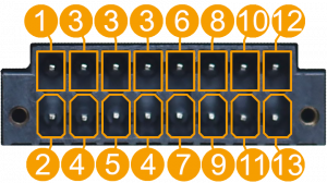
{{Template: Networking_{{lc:{{{series}}}}}_manual_power_socket_pinout}}{{#if: {{{rs|}}} | <br>{{Template:Networking_{{lc:{{{name}}}}}_manual_{{{rs}}}_pinout}} | }} | {{#ifeq: {{{series}}} | TRB2xx | {{Template: Networking_trb2xx_manual_16_pin_terminal_block_pinout}} | ||
|{{Template: Networking_{{lc:{{{series}}}}}_manual_power_socket_pinout}}{{#if: {{{rs|}}} | <br>{{Template:Networking_{{lc:{{{name}}}}}_manual_{{{rs}}}_pinout}} | }} | |||
{{#ifeq: {{{series}}} | TRB14x | {{#ifeq: {{{series}}} | TRB14x | ||
| {{Template: Networking_trb14x_first_start_device_configuration}} | | {{Template: Networking_trb14x_first_start_device_configuration}} | ||
Revision as of 14:34, 27 March 2020
This Wiki page contains the online version of the Quick Start Guide (QSG) for the {{{short_description}}}. Here you will find an overview of the various components found on the front and back sides of a {{{name}}} device, basic hardware installation, first login information, device specifications and general safety information. It is highly recommended that you acquaint yourself with with the Quick Start Guide before using the device. If you own a {{{name}}} device, you can also find a printed version of the Quick Start Guide in the device's package. [[File:{{{file_device}}}|{{{size_device}}}px|right]]
{{Template: Networking_{{{name}}}_manual_panels_front | file_front = {{{file_front}}} | size_front = {{{size_front}}} }}
{{Template: Networking_{{{name}}}_manual_panels_back | file_back = {{{file_back}}} | size_back = {{{size_back}}} }}
Connectors
{{#ifeq: {{{series}}} | TRB2xx |
|{{Template: Networking_{{{series}}}_manual_power_socket_pinout}} {{Template: Networking_{{{series}}}_first_start_hardware_installation
       | name     = {{{name}}}
       | series   = {{{series}}}
       | file_sim = {{{file_sim}}}
       | size_sim = {{{size_sim}}}
     }}
{{Template: Networking_{{{name}}}_first_start_configure_your_computer | name = {{{name}}}}}
{{Template: Networking_{{{name}}}_first_start_safety_information}}
[[Category:{{{name}}}]]

