TRM250 First Start: Difference between revisions
m Protected "TRM250 First Start" ([Edit=Allow only administrators] (indefinite) [Move=Allow only administrators] (indefinite)) |
|||
| Line 1: | Line 1: | ||
This Wiki page contains the online version of the '''Quick Start Guide''' ('''QSG''') for the '''TRM250 LTE Ethernet Gateway'''. Here you will find an overview of the various components found on the front and back sides of a TRB140 device, basic hardware installation, first login information, device specifications and general safety information. It is highly recommended that you acquaint yourself with with the Quick Start Guide before using the device. If you own a TRB140 device, you can also find a printed version of the Quick Start Guide in the device's package. | This Wiki page contains the online version of the '''Quick Start Guide''' ('''QSG''') for the '''TRM250 LTE Ethernet Gateway'''. Here you will find an overview of the various components found on the front and back sides of a TRB140 device, basic hardware installation, first login information, device specifications and general safety information. It is highly recommended that you acquaint yourself with with the Quick Start Guide before using the device. If you own a TRB140 device, you can also find a printed version of the Quick Start Guide in the device's package. | ||
| Line 8: | Line 9: | ||
<table class="nd-othertables"> | <table class="nd-othertables"> | ||
<tr> | <tr> | ||
<th style="width: 50px;" >No.</th> | <th style="width: 50px;">No.</th> | ||
<th style="width: 300px;">Description</th> | <th style="width: 300px;">Description</th> | ||
<th style="width: 550px; border-bottom: 1px solid white; | <th rowspan="5" style="width: 550px; border-bottom: 1px solid white;">[[File:Modem_trm250_manual_panels_front_v1.png|right]]</th> | ||
</tr> | </tr> | ||
<tr> | <tr> | ||
| Line 18: | Line 19: | ||
<tr> | <tr> | ||
<td>2</td> | <td>2</td> | ||
<td> | <td>Network LED</td> | ||
</tr> | </tr> | ||
<tr> | <tr> | ||
<td>3</td> | <td>3</td> | ||
<td> | <td>USB connector</td> | ||
</tr> | </tr> | ||
<tr style="border: 0"> | <tr style="border: 0"> | ||
| Line 35: | Line 36: | ||
<table class="nd-othertables"> | <table class="nd-othertables"> | ||
<tr> | <tr> | ||
<th style="width: 50px;" >No.</th> | <th style="width: 50px;">No.</th> | ||
<th style="width: 300px;">Description</th> | <th style="width: 300px;">Description</th> | ||
<th style="width: 550px; border-bottom: 1px solid white; | <th rowspan="3" style="width: 550px; border-bottom: 1px solid white;">[[File:Modem_trm240_manual_panels_back_v1.jpg|right]]</th> | ||
</tr> | </tr> | ||
<tr> | <tr> | ||
<td>1</td> | <td>1</td> | ||
<td>Mobile antenna connector</td> | <td>Mobile antenna connector</td> | ||
</tr> | </tr> | ||
<tr style="border: 0"> | <tr style="border: 0"> | ||
| Line 75: | Line 56: | ||
{| class="wikitable" | {| class="wikitable" | ||
|+ | |+ | ||
! style="background: white;" | ! colspan="2" style="background: white;" |Radio specifications | ||
|- | |- | ||
| style="text-align: left; background: white;" | RF technologies | | style="text-align: left; background: white;" |RF technologies | ||
| style="text-align: left; background: white;" | GSM, GPRS, EDGE, UMTS/HSPA+, LTE | | style="text-align: left; background: white;" |GSM, GPRS, EDGE, UMTS/HSPA+, LTE | ||
|- | |- | ||
| style="text-align: left; background: white;" | Max. RF power | | style="text-align: left; background: white;" |Max. RF power | ||
| style="text-align: left; background: white;" | 32 dBm@GSM, 24 dBm@WCDMA, 23 dBm@LTE | | style="text-align: left; background: white;" |32 dBm@GSM, 24 dBm@WCDMA, 23 dBm@LTE | ||
|- | |- | ||
! style="background: white;" | ! colspan="2" style="background: white;" |Bundled accessories specifications<span class="asterisk">*</span> | ||
|- | |- | ||
| style="text-align: left; background: white;" | Power | | style="text-align: left; background: white;" |Power | ||
| style="text-align: left; background: white;" | AC/DC power adapter 9 V, 1 A, 4 pin plug | | style="text-align: left; background: white;" |AC/DC power adapter 9 V, 1 A, 4 pin plug | ||
|- | |- | ||
| style="text-align: left; background: white;" | GSM/WCDMA/LTE antenna | | style="text-align: left; background: white;" |GSM/WCDMA/LTE antenna | ||
| style="text-align: left; background: white;" | 698~868/1850~2690 MHz, 50 Ω, VSWR ≤ 2, gain<span class="asterisk">**</span> 2 dBi, omnidirectional, SMA male connector | | style="text-align: left; background: white;" |698~868/1850~2690 MHz, 50 Ω, VSWR ≤ 2, gain<span class="asterisk">**</span> 2 dBi, omnidirectional, SMA male connector | ||
|- | |- | ||
|} | |} | ||
Revision as of 09:07, 25 November 2019
Main Page > TRM Modems > TRM250 > TRM250 First StartThis Wiki page contains the online version of the Quick Start Guide (QSG) for the TRM250 LTE Ethernet Gateway. Here you will find an overview of the various components found on the front and back sides of a TRB140 device, basic hardware installation, first login information, device specifications and general safety information. It is highly recommended that you acquaint yourself with with the Quick Start Guide before using the device. If you own a TRB140 device, you can also find a printed version of the Quick Start Guide in the device's package.
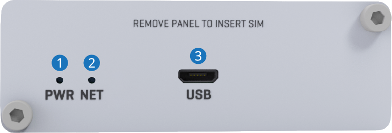
Front view
| No. | Description |  |
|---|---|---|
| 1 | Power LED | |
| 2 | Network LED | |
| 3 | USB connector | |
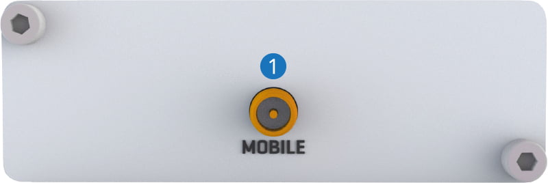
Back view
| No. | Description |  |
|---|---|---|
| 1 | Mobile antenna connector | |
Safety information
TRB140 gateway must be used in compliance with any and all applicable national and international laws and with any special restrictions regulating the utilixation of the communication module in prescribed applications and environments.
| Radio specifications | |
|---|---|
| RF technologies | GSM, GPRS, EDGE, UMTS/HSPA+, LTE |
| Max. RF power | 32 dBm@GSM, 24 dBm@WCDMA, 23 dBm@LTE |
| Bundled accessories specifications* | |
| Power | AC/DC power adapter 9 V, 1 A, 4 pin plug |
| GSM/WCDMA/LTE antenna | 698~868/1850~2690 MHz, 50 Ω, VSWR ≤ 2, gain** 2 dBi, omnidirectional, SMA male connector |
* Order code dependent.
** Higher gain antenna can be connected to compensate for cable attenuation when a cable is used. The user is responsible for the compliance with the legal regulations.
This sign on the package means that is necessary to read the User's Manual before you start using the device

