Template:Networking rutx configuration example openvpn bridge use case: Difference between revisions
No edit summary |
|||
| Line 32: | Line 32: | ||
<tr> | <tr> | ||
<th width=525; style="border-bottom: 1px solid white;></th> | <th width=525; style="border-bottom: 1px solid white;></th> | ||
<th width=620; style="border-bottom: 1px solid white;" rowspan=2>[[File: | <th width=620; style="border-bottom: 1px solid white;" rowspan=2>[[File:Networking_rutx_configuration_example_openvpn_bridge_use_case_1_v1.png|border|class=tlt-border|550px|right]]</th> | ||
</tr> | </tr> | ||
<tr> | <tr> | ||
| Line 50: | Line 50: | ||
<tr> | <tr> | ||
<th width=525; style="border-bottom: 1px solid white;></th> | <th width=525; style="border-bottom: 1px solid white;></th> | ||
<th width=620; style="border-bottom: 1px solid white;" rowspan=2>[[File: | <th width=620; style="border-bottom: 1px solid white;" rowspan=2>[[File:Networking_rutx_configuration_example_openvpn_bridge_use_case_2_v1.png|border|class=tlt-border|550px|right]]</th> | ||
</tr> | </tr> | ||
<tr> | <tr> | ||
| Line 67: | Line 67: | ||
<tr> | <tr> | ||
<th width=525; style="border-bottom: 1px solid white;></th> | <th width=525; style="border-bottom: 1px solid white;></th> | ||
<th width=620; style="border-bottom: 1px solid white;" rowspan=2>[[File: | <th width=620; style="border-bottom: 1px solid white;" rowspan=2>[[File:Networking_rutx_configuration_example_openvpn_bridge_use_case_3_v1.png|border|class=tlt-border|550px|right]]</th> | ||
</tr> | </tr> | ||
<tr> | <tr> | ||
| Line 81: | Line 81: | ||
<tr> | <tr> | ||
<th width=525; style="border-bottom: 1px solid white;></th> | <th width=525; style="border-bottom: 1px solid white;></th> | ||
<th width=620; style="border-bottom: 1px solid white;" rowspan=2>[[File: | <th width=620; style="border-bottom: 1px solid white;" rowspan=2>[[File:Networking_rutx_configuration_example_openvpn_bridge_use_case_4_v1.png|border|class=tlt-border|550px|right]]</th> | ||
</tr> | </tr> | ||
<tr> | <tr> | ||
| Line 95: | Line 95: | ||
<tr> | <tr> | ||
<th width=525; style="border-bottom: 1px solid white;></th> | <th width=525; style="border-bottom: 1px solid white;></th> | ||
<th width=620; style="border-bottom: 1px solid white;" rowspan=2>[[File: | <th width=620; style="border-bottom: 1px solid white;" rowspan=2>[[File:Networking_rutx_configuration_example_openvpn_bridge_use_case_5_v1.png|border|class=tlt-border|550px|right]]</th> | ||
</tr> | </tr> | ||
<tr> | <tr> | ||
Revision as of 17:14, 5 May 2020
 |
|
|---|---|
|
|
Configuration overview and prerequisites
Prerequisites:
- One RUTxxx router
- A Public Static or Public Dynamic IP addresses
- An end device to configure the router (PC, Laptop, Tablet, Smartphone)
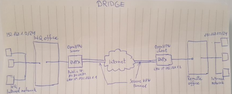
The topology above depicts the OpenVPN scheme. The router with the Public IP address ({{{name}}}) acts as the OpenVPN server and other {{{name}}} acts as client. OpenVPN connects the networks of HQ Office and Remote Office.
When the scheme is realized, remote office workers will be able to reach HQ’s internal network with all internal systems, allowing working from remote office to be possible. All remote office's WAN and LAN traffic is going to travel through VPN tunnel.
Configuring HQ office router
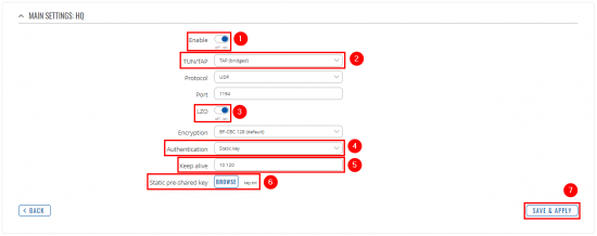
OpenVPN
 |
|
|---|---|
|
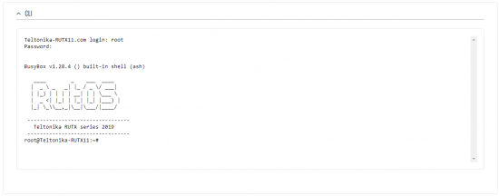
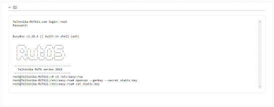
Login to the router's WebUI, navigate to the Services → CLI page and do the following:
|
 |
|
|---|---|
|
Write the following commands to create and open OpenVPN Static key, which will be used for authentication: 1) cd /etc/easy-rsa 2) openvpn --genkey --secret static.key 3) cat static.key |
 |
|
|---|---|
|
Create .txt file on your computer and copy Static key to it. Copy from the beginning to the end as in the example. |
Configuring remote office router
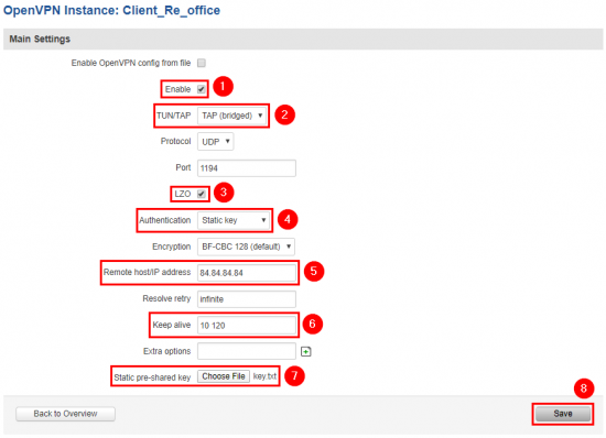
OpenVPN
LAN
 |
|
|---|---|
|
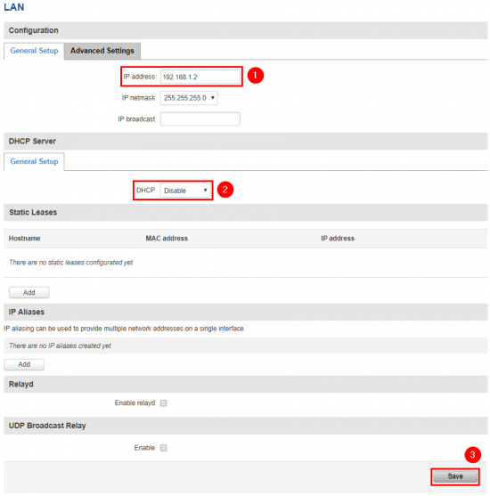
Now go to Network → LAN and apply the following steps:
|


