Tinc VPN configuration examples: Difference between revisions
| Line 179: | Line 179: | ||
* 2. Open ''Allow forward to destination zones'' list. | * 2. Open ''Allow forward to destination zones'' list. | ||
* | * 3. Select '''lan''' zone, this will allow us to access LAN network from outside via tinc VPN. | ||
[[File:Tincfirewall3.png]] | [[File:Tincfirewall3.png]] | ||
Revision as of 11:20, 30 September 2022
Main Page > General Information > Configuration Examples > VPN > Tinc VPN configuration examplesIntroduction
tinc is a Virtual Private Network (VPN) daemon that uses tunneling and encryption to create a secure private network between hosts on the Internet. tinc is Free Software and licensed under the GNU General Public License version 2 or later. Because the VPN appears to the IP level network code as a normal network device, there is no need to adapt any existing software. This allows VPN sites to share information with each other over the Internet without exposing any information to others. This article provides an extensive configuration example with details on how to create a tunnel connection between two tinc instances, both of which configured on RUTxxx routers.
Configuration overview and prerequisites
Before we begin, let's overview the configuration that we are attempting to achieve and the prerequisites that make it possible.
Prerequisites:
- Two RUTxxx routers or TRB gateways of any type
- At least one router must have a Public Static or Public Dynamic IP address
- At least one end device (PC, Laptop, Tablet, Smartphone) to configure the routers
- (Optional) A second end device to configure and test remote LAN access
There will be two tinc configuration schemes presented. Although the second scheme is only an extension of the first one. Therefore, to configure the second scheme, you will have to configure the first as well.
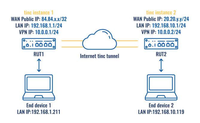
Topology 1:
The figure above depicts two RUTxxx routers (RUT1 and RUT2) connected by an tinc tunnel via the Internet.
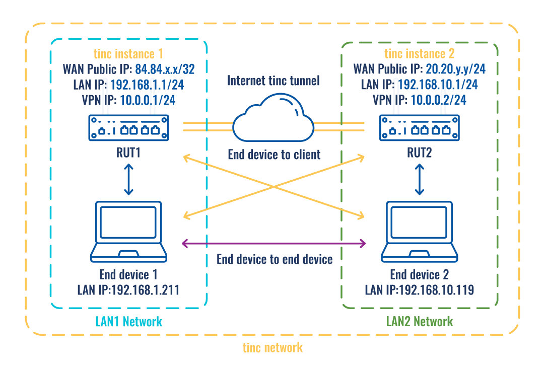
Topology 2:
As mentioned earlier, configuration scheme 2 (figure above) is an extension of configuration scheme 1. While configuration scheme 1 only depicts a connection between two tinc instances, you can see that configuration scheme 2 includes additional two end devices (END1 and END2), each connected to a separate router's LAN. When this topology is set up, not only will the two routers be able to communicate with each other, but the end devices will also be reachable to one another and from each router.
In addition to traffic encryption, tinc VPN also supports automatic full mesh routing - VPN traffic is always (if possible) sent directly to the destination, without going through intermediate hops.
Furthermore, it is easily expandable – to add a new node, all you have to do is to create an extra configuration file.
A tunnel is more widely implemented in site-to-site VPN scenarios and supports NAT traversal.
Router configuration
If you have familiarized yourself with the configuration schemes and have all of the devices in order, we can start configuring the routers using the instructions provided in this section.
Basic tunnel
First of, lets configure a simple connection between two tinc instances, i.e., RUT1 and RUT2 as described above in configuration scheme 1.
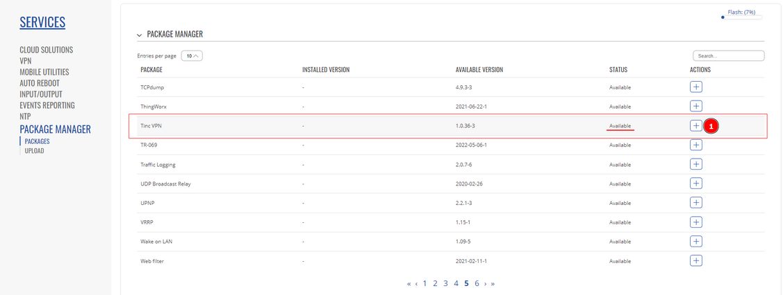
1. tinc is not installed on our devices, therefore, it has to be installed via the package manager. Services -> Package Manager -> Packages and search for tinc VPN and press + to install.
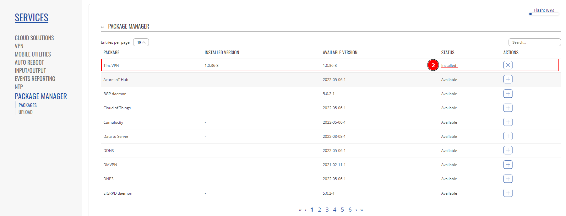
2. After successful installation, package status should be changed to Installed.
- In Network -> Firewall -> General you should see a new Firewall zone “tinc” created:
- Lastly, in Network -> Firewall -> Traffic rules a new traffic rule added:
- From this point onwards, all configuration will be made using command line interface.
- Make a folder for your tinc daemon where all your configurations will be kept. This procedure is required if you’re going to run more than one tinc daemon on one PC. However, if you only need one instance, then you can keep all configuration in default directory at “/etc/tinc/”
- Use mkdir to create a new folder at /etc/tinc/
- Then use your favorite text editor (I’m using vi) and create tinc.conf (If you skipped making specific folder, then you can create configs as mentioned earlier – in parent folder “vi /etc/tinc/tinc.conf”, otherwise do it in "vi /etc/tinc/example/tinc.conf"
- And on RUT2 use a different name (ex. rut2) and add the line “ConnectTo = rut1”
- Name your device, specify address family, and interface. Try not to set the interface to “tun0” as it is a system reserved interface and may not work with this VPN.
- Then on RUT1 create tinc-up script, which will turn on your VPN interface.
“vi /etc/tinc/example/tinc-up”
#!/bin/sh
ifconfig $INTERFACE 10.0.0.1 netmask 255.255.255.0
- On RUT2 do the same, just change the VPN IP.
#!/bin/sh
ifconfig $INTERFACE 10.0.0.2 netmask 255.255.255.0
- Accordingly, on both routers create a tinc-down script, which will turn off said VPN interface
“vi /etc/tinc/example/tinc-down”
#!/bin/sh
ip link set $INTERFACE down
- Set permissions to your scripts using “chmod 755 /etc/tinc/example/tinc-*”
- Now, create last configuration files. First, create a folder for all the hosts and their info, then create a host file using text editor.
"mkdir /etc/tinc/example/hosts/"
On rut1:
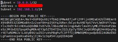
"vi /etc/tinc/example/hosts/rut1"
Subnet = 10.0.0.1/32
Address = 84.84.84.84
On rut2:
"vi /etc/tinc/example/hosts/rut2"
Subnet = 10.0.0.2/32
Address = 80.80.100.100 (Optional)
- After creating host files, generate public/private keypair
tincd -n netname -K , in our scenario: “tincd -n example -K” and simply press enter to accept the default.
- After keypairs were generated, you need to copy the device’s host file to the other device. Copy RUT1’s hosts/rut1 file to RUT2 and place it in the same folder hosts/ and do the same with the RUT2 file placing it in the RUT1 hosts folder.
You can do this with WinSCP, or using CLI’s scp to transfer files from one device to the other.
Here on CLI, In 1st picture, I used scp to transfer RUT1’s host file directly to my RUT2, because RUT1 has public IP and therefore, I can directly communicate with it, and later, transferred RUT2’s host file to the RUT1 in the 2nd picture.
- After both host files were shared between two devices, we can start our tinc instances. “tincd -n netname”, or in our case “tincd -n example”, additionally, I recommend using debug mode, to check whether there are any connectivity errors “tincd -n example -D -d3” (d3 – debug level 3)
RUT1:
RUT2:
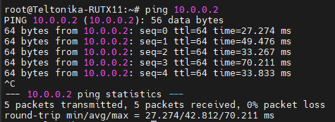
Also, you can ping RUT1’s or 2’s VPN IP, here I ping RUT2 from RUT1, it should work both ways:
And you can see a new route created on tinc0 interface:
End-client to end-client example
We’ll continue with our previous configurations.
- Update your host file in hosts/ by adding your LAN network.
hosts/rut1 file:
hosts/rut2 file:
- Add a route to other’s device LAN network through your tinc interface:
Add a line to your tinc-up script, so that a route will be added when tinc is started.
on rut1 example/tinc-up
on rut2 example/tinc-up
- However, you’ll only be able to reach each other’s device LAN IP, but not the end devices. Therefore you need to change firewall rules.
FIREWALL
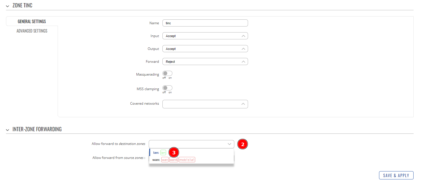
- To achieve end-to-end client communication you need to configure the tinc zone Network->Firewall->General, that was created at the installation. Press the edit button to configure it.
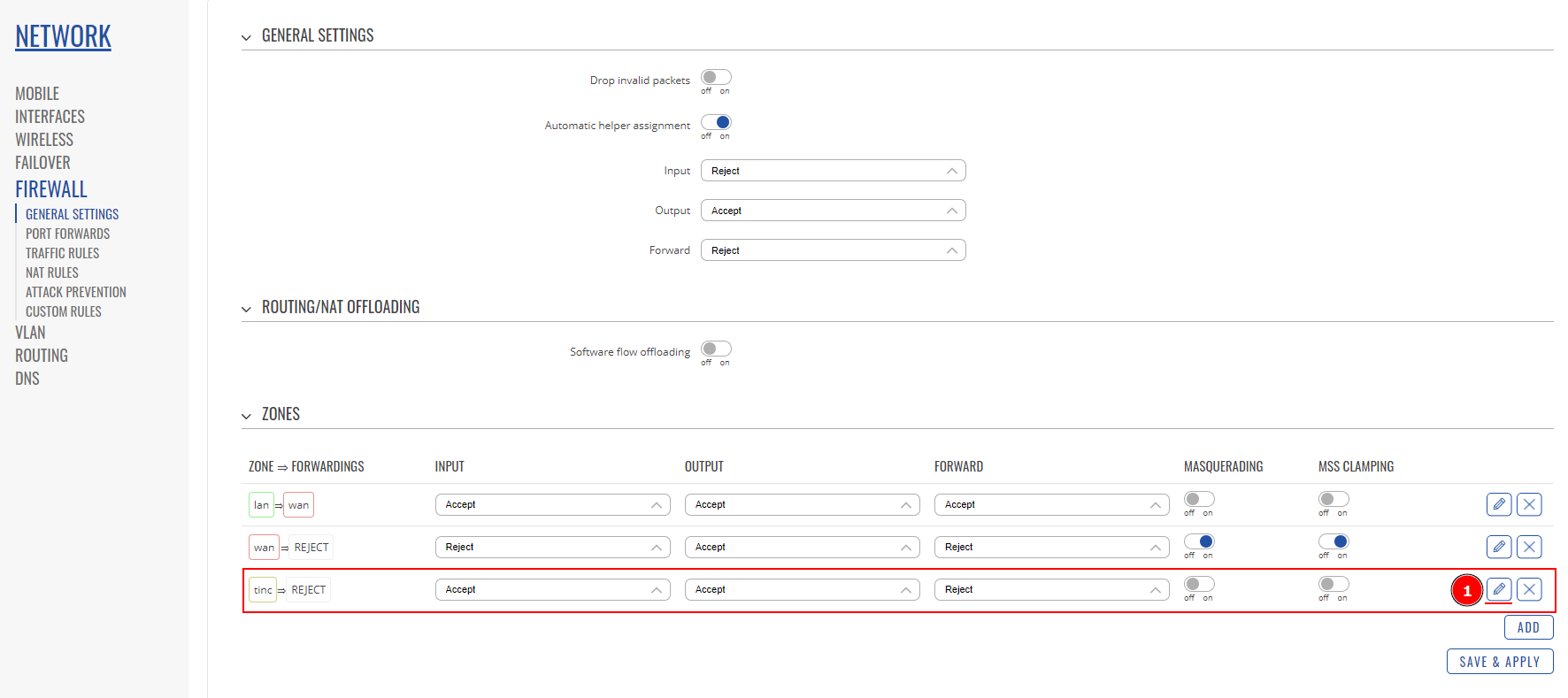
- 2. Open Allow forward to destination zones list.
- 3. Select lan zone, this will allow us to access LAN network from outside via tinc VPN.
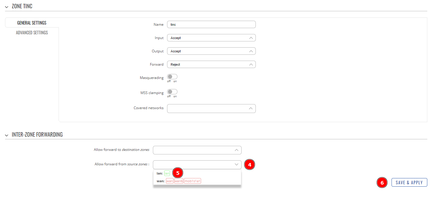
- 4. Open Allow forward from source zones list.
- 5. Select lan zone, so we can access outside networks via tinc VPN too.
- 6. Press Save & Apply
We are going to allow all forwards via this interface, including lan and wan networks into this zone. This way we can communicate from END1 to RUT2’s lan as well as END2 and vice versa. In short LAN1 <-> WAN1 <- through tinc tunnel -> WAN2 <-> LAN2


