Ignition detection solution: Difference between revisions
Justas.Cip (talk | contribs) m (Justas.Cip moved page Ignition detection configuration example to Draft:Ignition detection configuration example without leaving a redirect) |
Justas.Cip (talk | contribs) No edit summary |
||
| Line 20: | Line 20: | ||
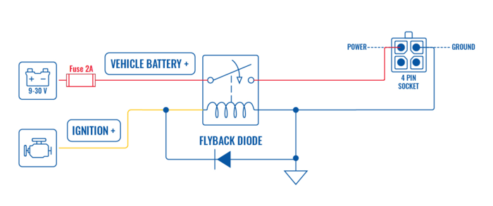
The first schematic diagram provided gives you the ability to turn the device on and off depending on ignition state. | The first schematic diagram provided gives you the ability to turn the device on and off depending on ignition state. | ||
[[File:Ignitionstateschematic.jpg|700px|border|class=tlt-border]] | |||
To build this schematic, you would need two electrical components: | To build this schematic, you would need two electrical components: | ||
| Line 31: | Line 31: | ||
Relay choice depends on vehicle's electrical system voltage. If this setup is installed into a Vehicle with 12 V system, then a relay similar to the [https://www.digikey.com/en/products/detail/panasonic-electric-works/CB1-12V/646971 CB1-12V] could be used. Otherwise, if the electrical system is 24 V, a relay similar to the [https://www.digikey.com/en/products/detail/panasonic-electric-works/CB1-24V/646972 CB1-24V] could be used. When choosing a relay, the most important aspect is '''Coil Voltage''', therefore I recommend using aforementioned relays based on the voltage. | Relay choice depends on vehicle's electrical system voltage. If this setup is installed into a Vehicle with 12 V system, then a relay similar to the [https://www.digikey.com/en/products/detail/panasonic-electric-works/CB1-12V/646971 CB1-12V] could be used. Otherwise, if the electrical system is 24 V, a relay similar to the [https://www.digikey.com/en/products/detail/panasonic-electric-works/CB1-24V/646972 CB1-24V] could be used. When choosing a relay, the most important aspect is '''Coil Voltage''', therefore I recommend using aforementioned relays based on the voltage. | ||
When building this schematic, you can ground the device and the relay on the same spot, for example, chassis of the vehicle. | |||
----- | ----- | ||
| Line 36: | Line 38: | ||
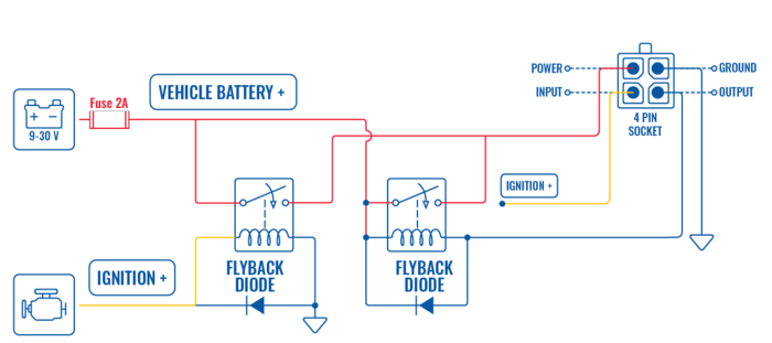
The second schematic diagram provided gives you the ability to turn the device on with the ignition and turn off only when certain preset time expires after the ignition is turned off. | The second schematic diagram provided gives you the ability to turn the device on with the ignition and turn off only when certain preset time expires after the ignition is turned off. | ||
[[File:Schematicdelayoff.jpg|700px|border|class=tlt-border]] | |||
To build this schematic, you would need to use the same electrical components as mentioned above, only in this case we will use 2 Relays and 2 Diodes. As mentioned earlier, '''using this schematic without the diode, raises risk damaging the device.''' | To build this schematic, you would need to use the same electrical components as mentioned above, only in this case we will use 2 Relays and 2 Diodes. As mentioned earlier, '''using this schematic without the diode, raises risk damaging the device.''' | ||
When building this schematic, make sure to ground only one relay and the device (these can be grounded at the same spot), notice that the secondary relay (on the right) gets ground from the device's output - this allows controlling the relay and delay the turning off time. Also, notice that ignition is connected both to the device input and to the first relay - this can be done from the same ignition source - there is no need to search for separate wires. | |||
==Device configuration== | ==Device configuration== | ||
| Line 97: | Line 101: | ||
[[File:Jugglerinstance.png|border|class=tlt-border]] | [[File:Jugglerinstance.png|border|class=tlt-border]] | ||
With that, the configuration is finished. The device will stay on for as long as '''Execution delay''' value is set. | With that, the configuration is finished. The device will stay on for as long as '''Execution delay''' value is set. If this example is not working as intended, please review the steps once again. | ||
Revision as of 09:39, 29 November 2022
Main Page > General Information > Configuration Examples > Hardware application > Ignition detection solutionIntroduction
Ignition detection is a useful feature that we can implement into our connectivity solutions with some additional electrical components. In this article, we will show you two options on how to run the device depending on the state of Ignition:
- 1st option - the device turns on with the ignition and turns off when the ignition goes off.
- 2nd option - the device turns on with the ignition and stays on for some time, even if the ignition is turned off.
This example will use the 4-pin connector, available on most of the Teltonika networking devices:
To access the I/O pins and power the device at the same time you would likely need one of these adaptors from our Accessories list:
- POWER CABLE WITH 4-WAY SCREW TERMINAL
- POWER CABLE WITH 4-WAY OPEN WIRE
- 4-PIN POWER ADAPTER WITH I/O ACCESS
Schematics
The first schematic diagram provided gives you the ability to turn the device on and off depending on ignition state.
To build this schematic, you would need two electrical components:
- Diode
1N4001 diode or similar could be used. It is used to protect the control circuit from the sudden voltage spike. If the relay that you are using has a flyback diode built in, this diode is not needed. NOTE: if you are using this schematic without the diode, you risk damaging the device.
- Electromagnetic Relay
Relay choice depends on vehicle's electrical system voltage. If this setup is installed into a Vehicle with 12 V system, then a relay similar to the CB1-12V could be used. Otherwise, if the electrical system is 24 V, a relay similar to the CB1-24V could be used. When choosing a relay, the most important aspect is Coil Voltage, therefore I recommend using aforementioned relays based on the voltage.
When building this schematic, you can ground the device and the relay on the same spot, for example, chassis of the vehicle.
The second schematic diagram provided gives you the ability to turn the device on with the ignition and turn off only when certain preset time expires after the ignition is turned off.
To build this schematic, you would need to use the same electrical components as mentioned above, only in this case we will use 2 Relays and 2 Diodes. As mentioned earlier, using this schematic without the diode, raises risk damaging the device.
When building this schematic, make sure to ground only one relay and the device (these can be grounded at the same spot), notice that the secondary relay (on the right) gets ground from the device's output - this allows controlling the relay and delay the turning off time. Also, notice that ignition is connected both to the device input and to the first relay - this can be done from the same ignition source - there is no need to search for separate wires.
Device configuration
If you chose the first option, no additional device configuration is needed. If you would like a set up based on the second schematic, you would need to do additional configuring in the device.
Startup script
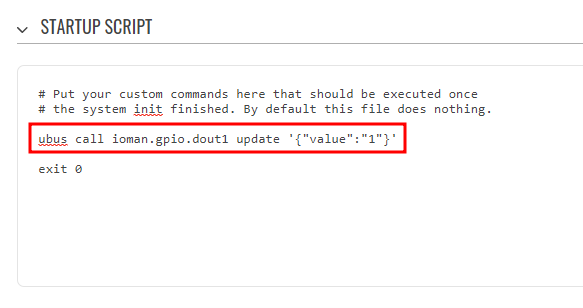
First of all, we need a custom startup script to toggle a second relay to ON position. Follow these steps to configure startup behavior:
- Navigate to System -> Custom scripts -> Startup script.
- Above the exit 0 text, input command to turn on the output Pin: ubus call ioman.gpio.dout1 update '{"value":"1"}'
- Press Save & Apply.
Input/Output Juggler configuration
Input/Output configuration also needs some changes for this functionality to work as intended.
- Navigate to Services -> Input/Output -> IO Juggler.
- In the general tab, press enable to turn on I/O Juggler functionality.
Action configuration
- Navigate to Actions tab.
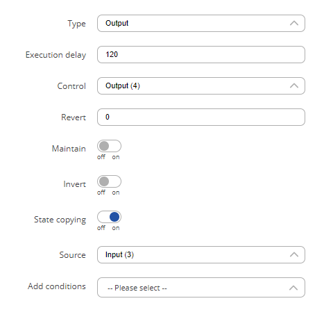
- In the Add new instance section, input name (delayoff in this example) for action and in Type select Output, press Add.
In the new window, configure the settings according to the explanations below.
- Type: Output.
- Execution delay (how long you would like to keep the router on after the ignition turns off): your preferred time in seconds.
- Control: Output (4) (Output pin on which the relay control is connected).
- State: Low.
Leave everything else as default, press Save & Apply.
Instance configuration
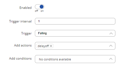
Switch back to the General tab. In the Add new instance section, select Role: Input(3) and press Add to add new instance.
In the new window, configure the settings according to the explanations below.
- Press Enable to enable the instance.
- Trigger interval – 1 (you could input a higher value, for example, if you are connecting to ACC and input signal goes off for a second when starting the vehicle - it would allow the Output Pin state remain static in the starting moment).
- Trigger – Falling (reacts when Ignition state goes from On to Off).
- Add actions – select the action which you‘ve created previously (delayoff in this example).
- Press Save & Apply.
With that, the configuration is finished. The device will stay on for as long as Execution delay value is set. If this example is not working as intended, please review the steps once again.


