RUTM54 DLMS
The information in this page is updated in accordance with firmware version RUTM_R_00.07.11.4.
Summary
The DLMS / COSEM standard suite (IEC 62056 / EN 13757- 1) is the most widely accepted international utility meter data exchange standard. DLMS is the application layer protocol that transforms the data into messages and COSEM describes the general object model and can be used for all kinds of presentations.
This manual page provides an overview of the DLMS functionality in RUTM54 devices.
Note: DLMS is additional software that can be installed from the System → Package Manager page. Note: The count of DLMS connections is limited to 30, physical devices - up to 30, space groups - up to 10, cosem objects - up to 20 in each group.
Main
The Main page is used to configure DLMS physical devices and Cosem Groups.
General status
This section displays DLMS general status information.
Notice the Global section config. It is used to outright turn the service off or on if any active configurations are present.
Clicking the Cog icon opens a modal window. The global configuration slider can be set and it's state saved.
DLMS Physical devices
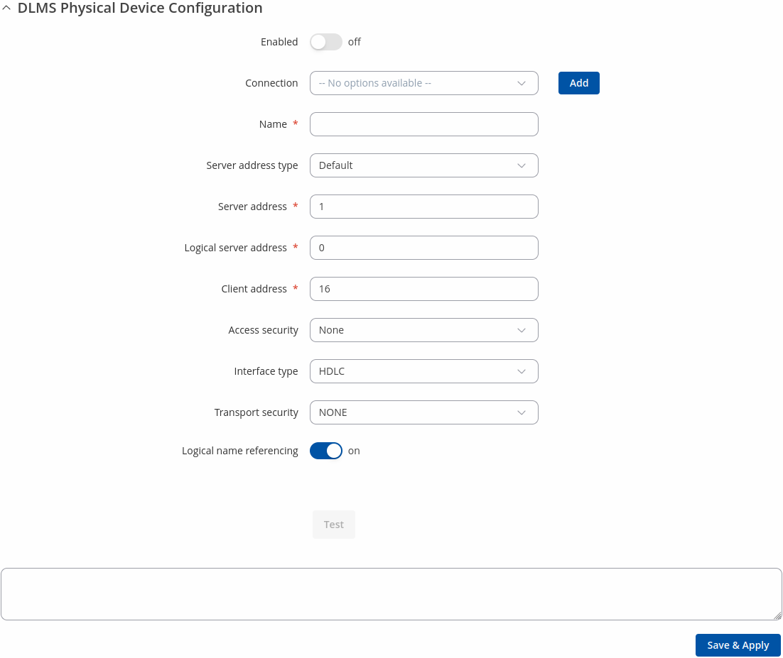
Interoperable devices in DLMS categorize as server (physical device) and client. Data collection device act as a client that supports system dependent features, parameters, functions and classes requesting data from the server (physical device). In this structure, communication protocol stack is independent of application layer so both devices may communicate different media. To add a new physical device, click the 'Add' button.
After clicking 'Add' you will be redirected to the newly added physical device's configuration page.
| Field | Value | Description |
|---|---|---|
| Enable | off | on; default: off | Enables specific physical device configuration. |
| Connection | empty ; default: none | DLMS connection. |
| Name | string; default: none | Physical device name. |
| Server address type | Default | Serial number; default: Default | Select 'Default' for server address or 'Serial Number' for addressing by a specific serial number. |
| Server address | integer [0..255]; default: 1 | DLMS device server address. |
| Serial number | unsigned integer; default: 1 | DLMS device serial number. Uses formula 'SN % 10000 + 1000'. |
| Logic server address | integer [0..255]; default: 0 | DLMS device logical server address. |
| Client address | integer [0..255]; default: 16 | DLMS device client address. |
| Access security | none | Low | High | High MD5 | High SHA1 | High GMAC | HIGH SHA256; default: none | DLMS device authentication type. |
| Password | string; default: none | DLMS device password if authentication is used. |
| Interface type | HDLC | WRAPPER; default: HDLC | DLMS device interface type. |
| Transport security | none | Authentication | Encryption | Authentication encryption; default: none | DLMS device message encryption. |
| Authentication/Encryption/Authentication encryption: Invocation counter OBIS code | string; default: none | DLMS device invocation counter OBIS code. |
| Authentication/Authentication encryption: Authentication key | string (Length of the value must be 32); default: none | DLMS device authentication key. |
| Encryption/Authentication encryption: Block cipher key | string (Length of the value must be 32); default: none | DLMS device block cipher key. |
| Encryption/Authentication encryption: Dedicated key | string (Length of the value must be 32); default: none | DLMS device dedicated key. |
| Logical name referencing | on | off; default: on | DLMS devices use Logical Names to reference and access specific data objects or attributes during communication. For example, when requesting data from a device, you might reference a specific Logical Name to retrieve the information. |
| Test | -(interactive button) | Test device configuration. |
Scan device parameters
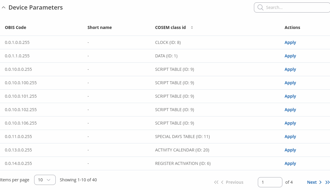
After successfully adding the 'DLMS physical devices' configuration, and if the DLMS server is available, you can initiate a Device Parameters scan, which will write the parameters locally next to the cosem value configuration.
DLMS Cosem groups
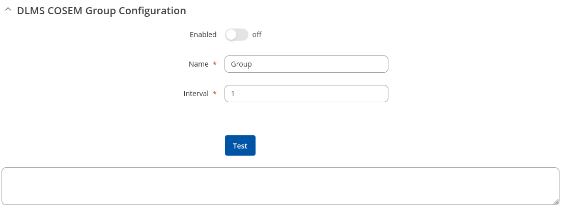
To add a new cosem group, click the 'Add' button.
After clicking 'Add' you will be redirected to the newly added cosem group's configuration page.
| Field | Value | Description |
|---|---|---|
| Enable | off | on; default: off | Enables Cosem group. |
| Name | string; default: none | OBIS code group name. |
| Interval | integer [1..4294967295]; default: 1 | Interval for OBIS code reading (in seconds). |
| Test | -(interactive button) | Test cosem group. |
DLMS Cosem value
Cosem value is a specific value retrieved from a defined server (physical device). To add a new cosem value, click the 'Add' button.
After clicking 'Add' you will be redirected to the newly added cosem value's configuration page.
| Field | Value | Description |
|---|---|---|
| Enable | off | on; default: off | Enables Cosem state. |
| Name | string; default: none | COSEM option name. |
| Physical device | selection; default: none | Physical device to read from. |
| OBIS code | string; default: none | OBIS code value, actions are not executed, only properties are read. |
| COSEM class id | DATA (ID: 1) | REGISTER (ID: 3) | EXTENDED REGISTER (ID: 4) | DEMAND REGISTER (ID: 5) | REGISTER ACTIVATION (ID: 6) | PROFILE GENERIC (ID: 7) | CLOCK (ID: 8) | SCRIPT TABLE (ID: 9) | SPECIAL DAYS TABLE (ID: 11) | ASSOCIATION LOGICAL NAME (ID: 15) | SAP ASSIGNMENT (ID: 17) | IMAGE TRANSFER (ID: 18) | IEC LOCAL PORT SETUP (ID: 19) | ACTIVITY CALENDAR (ID: 20) | REGISTER MONITOR (ID: 21) | ACTION SCHEDULE (ID: 22) | IEC HDLC SETUP (ID: 23) | IEC TWISTED PAIR SETUP (ID: 24) | UTILITY TABLES (ID: 26) | MODEM CONFIGURATION (ID: 27) | AUTO ANSWER (ID: 28) | AUTO CONNECT (ID: 29) | PUSH SETUP (ID: 40) | TCP UDP SETUP (ID: 41) | IP4 SETUP (ID: 42) | MAC ADDRESS SETUP (ID: 43) | GPRS SETUP (ID: 45) | GSM DIAGNOSTIC (ID: 47) | IP6 SETUP (ID: 48) | COMPACT DATA (ID: 62) | SECURITY SETUP (ID: 64) | ARBITRATOR (ID: 68) | DISCONNECT CONTROL (ID: 70) | LIMITER (ID: 71); default: DATA (ID: 1) | Object type for OBIS code. |
| Atributes | list; default: all | Available attributes for the selected COSEM class (check it here). |
| Entries | interger [1..32767]; default: none | How many data objects to read. |
Device Parameters
Parameters that are found after scan has finished.
Connections
The Connections page is used to configure DLMS connections. You can use either TCP or serial (depending on the router) connection to establish a connection between the physical device and the router.
General status
This section displays DLMS general status information.
DLMS Connections
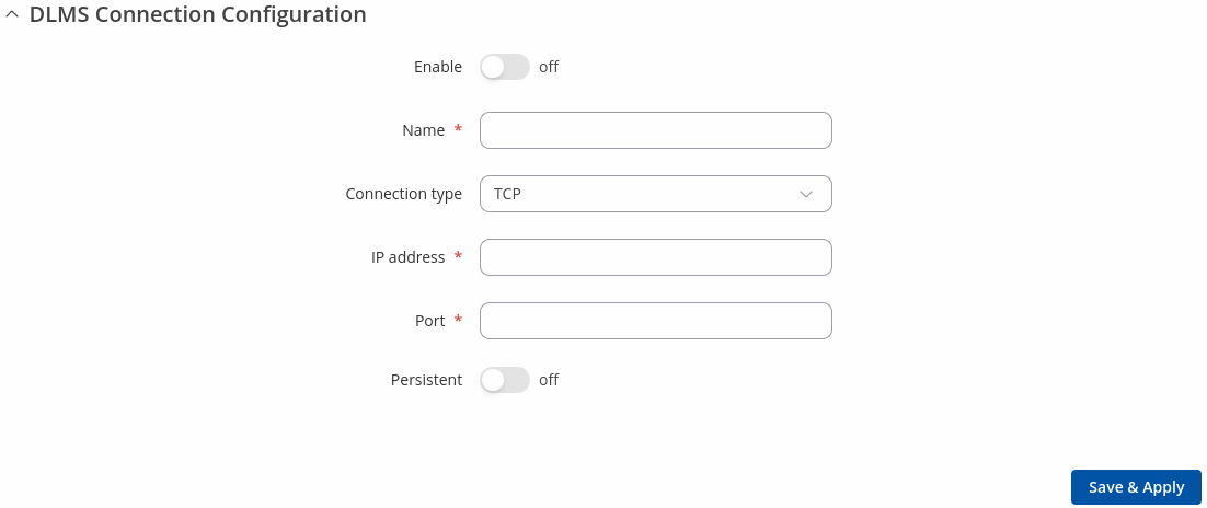
To add a new connection, click the 'Add' button.
After clicking 'Add' you will be redirected to the newly added connection's configuration page.
| Field | Value | Description |
|---|---|---|
| Enable | off | on; default: off | Enables Cosem state. |
| Name | string; default: previously added connection name | Name of DLMS connection configuration. |
| Connection type | TCP | Serial; default: TCP | DLMS connection type. |
| Serial device | USB RS232 interface; default: USB RS232 interface | DLMS serial device. |
| Baud rate | 300 | 1200 | 2400 | 4800 | 9600 | 19200 | 38400 | 57600 | 115200; default: 9600 | Serial data transmission rate (in bits per second). |
| Data bits | 5 | 6 | 7 |8; default: 8 | Number of data bits for each character. |
| Stop bits | 1| 2; default: 1 | Stop bits sent at the end of every character allow the receiving signal hardware to detect the end of a character and to resynchronise with the character stream. Electronic devices usually use one stop bit. Two stop bits are required if slow electromechanical devices are used. |
| Parity | Even | Odd| Mark | Space | None; default: None | In serial transmission, parity is a method of detecting errors. An extra data bit is sent with each data character, arranged so that the number of 1 bits in each character, including the parity bit, is always odd or always even. If a byte is received with the wrong number of 1s, then it must have been corrupted. However, an even number of errors can pass the parity check.
|
| Flow control | None | RTS/CTS | Xon/Xoff; default: None | In many circumstances a transmitter might be able to send data faster than the receiver is able to process it. To cope with this, serial lines often incorporate a "handshaking" method, usually distinguished between hardware and software handshaking.
|
| IP address | ip; default: none | DLMS device IP address for TCP connection. |
| Port | integer [1..65535]; default: none | DLMS device IP port for TCP connection. |
| Persistent | off | on; default: off | Open TCP connection once and reuse it between requests. |


