InterVLAN Routing On TSW212
Summary
In this example, we will show how to manage VLAN-to-VLAN communication while only using a manageable TSW device. A switch, by default, operates at Layer 2 of the OSI model, which means it forwards data frames based on MAC addresses within a single broadcast domain. VLANs (Virtual LANs) allow for the logical segmentation of this broadcast domain, creating separate broadcast groups to enhance security and manage network traffic more effectively. However, devices in different VLANs cannot communicate directly. This is where interVLAN routing is required. InterVLAN routing allows devices in different VLANs to exchange data packets by forwarding them through a Layer 3 device, usually a router or like in this case a layer 2 switch with some of the layer 3 functionalities.
Setting up VLANs
In this example, we will be setting up Tag-Based VLANs. This method lets us assign different VLANs to a single switch port, giving us more flexibility with our network layout.
Tag based VLAN setup
To create a VLAN follow all the steps below:
- Access your device via WebUI by typing your switch private IP in your browser.
- Next, navigate to Network → VLAN
- Now you will need to create 2 new VLAN’s by entering VLAN name (for example: VLAN2 and VLAN3) and clicking

- Press “Edit” button on your newly created VLAN instance.
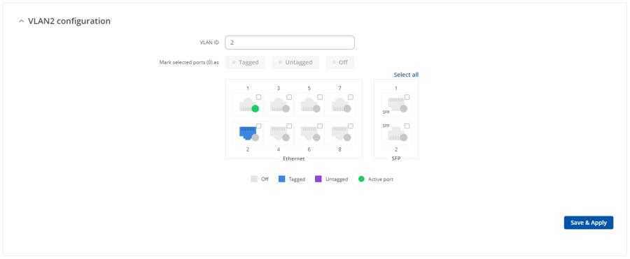
- Assign your VLAN ID to your preferred port (I have used port 2 for this example)
Creating VLAN interfaces
Navigate to Network → Interfaces
Add a new instance, by entering your preferred name and pressing the ![]() button.
button.
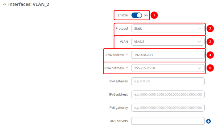
A new window for your interface configuration will pop up:
- Make sure you enable you interface.
- For a protocol select – Static.
- Select the VLAN you are making your interface for.
- Enter the IPV4 address of your choice (IP addresses of your VLAN subnets have to be different).
- Enter your preferred subnet mask for your IPV4 address (for example: if you have subnet 192.168.20.0 enter subnet mask 255.255.255.0).
Setting up DHCP servers
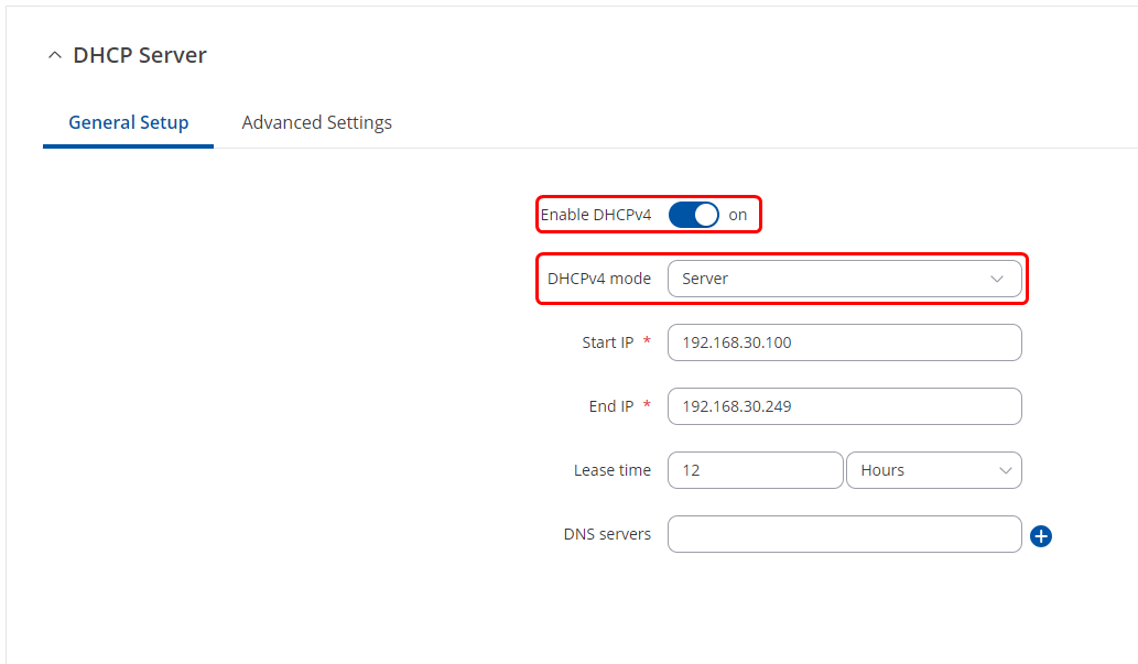
To set up DHCP servers for your created VLANs head to Network → DHCP and add new instance by selecting your created VLAN interfaces and clicking ![]() button.
button.
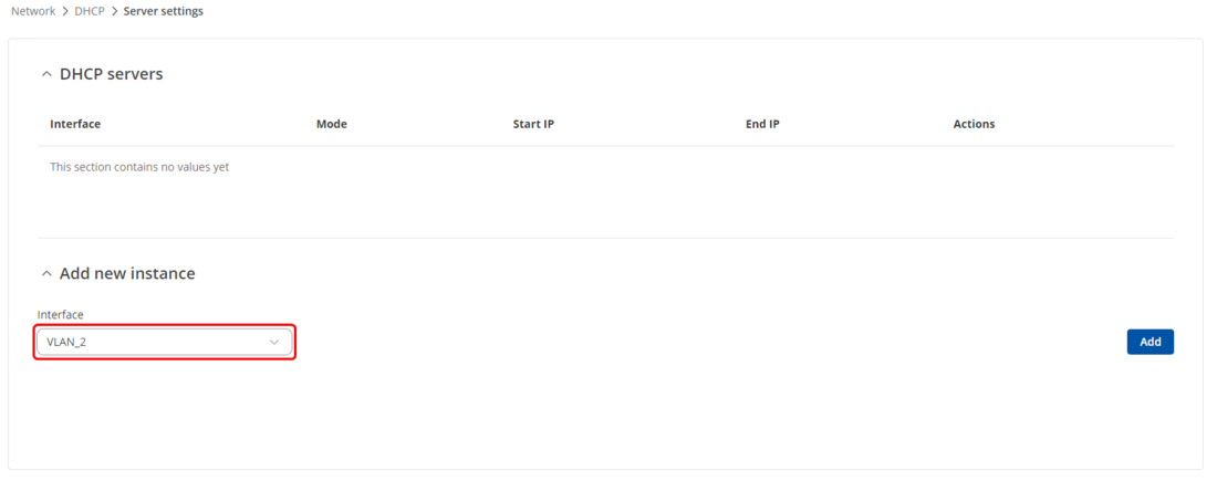 In the pop up window make sure DHCPv4 - enabled and DHCPv4 mode is selected as Server.
Static Routes
Static routes have to be set for subnets to allow communication between the VLANs.
- Head to the Network → Static Routes and create static routes for your VLAN subnets.
- Select interface – Your created VLAN interface (In this example VLAN2 and VLAN3).
- Enter the target IP address (the address of your VLAN subnet that you are trying to reach)
- Enter the target IPv4-netmask
- Enter IPv4-Gateway (the IP address of your VLAN interface which is used for leaving its network).
Once the static routes are created click on Save & Apply.

| Field | Value | Description |
|---|---|---|
| Interface | static | dhcp | dhcp6; default: static | The zone where the target network resides. |
| Target* | IPv4; default: none | Destination network address. |
| IPv4-Netmask* | netmask; default: none | A netmask is used to divide an IP address into sub-networks (subnets). Combined together, the 'Netmask' and 'Target' values define the exact destination network or IP address to which this route applies. |
| IPv4-Gateway | IPv4; default: none | A gateway can be any machine in a network that is capable of serving as an access point to another network. Traffic that matches this route will be directed over the IP address specified in this field. |
| Metric | integer [0..4294967295]; default: 1 | The metric value is used as a sorting measure. If a packet about to be routed fits two rules, the one with the lower metric is applied. |
| MTU | integer [68..9200]; default: 1500 | Sets the maximum transmission unit (MTU) size. It is the largest size of a protocol data unit (PDU) that can be transmitted in a single network layer transaction. |
| Route Type | unicast | local | broadcast | multicast | unreachable | prohibit | blackhole | anycast | -- custom -- ; default: unicast | Selects route type. Each type specifies a different behavior for the route:
|
Testing InterVLAN routing
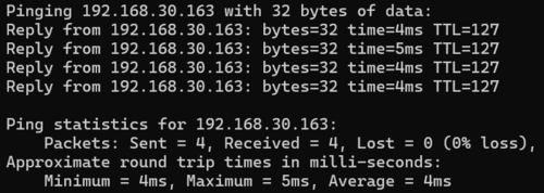
Once the VLANs and static routes are set up, we can test the communication between VLANs by pinging end devices from different VLANs.
