OSPF via VPLS and ZerotierVPN
Introduction
Consider a configuration option for a high-performance network with data link service backup. Since the expansion of the count of objects most often entails changes in the network configuration, setting up static routes, firewall rules, ACL, and so on. The dynamic route building protocol can help us, in this example, consider setting up OSPF on a network without a public IP addresses, with LTE channel redundancy.
Prerequisites:
- Two or more RUTxxx(RUTXxx) routers of any type (excluding RUT955)
- At least one end device (PC, Laptop, Tablet, Smartphone) to configure the routers
- VPLS or any L2/L3 type of wired data channel.
- Wired or wireless internet connection.
Summary
The Mobile page is used to configure mobile connection settings.
This manual page provides an overview of the Mobile page in {{{name}}} devices.
If you're having trouble finding this page or some of the parameters described here on your device's WebUI, you should turn on "Advanced WebUI" mode. You can do that by clicking the "Advanced" button, located at the top of the WebUI.
Configuration overview and prerequisites
Before we begin, let's overview the configuration that we are attempting to achieve and the prerequisites that make it possible.
- SCHEME
The figure above shows a diagram of connecting routers through a VPLS data link and a mobile connection. In this case, VPLS unites routers via L2 connectivity, and connectivity through a mobile network (with private IP addresses) is provided by Zerotier VPN. When the scheme is implemented, the routing received over OSPF is built dynamically by sending broadcast packets between L2 networks. Since Remote Clients are connected to the same network, 2 routes will be installed for each object, through VPLS and through Zerotier. And since VPLS will provide the lowest level of delay, we will give priority to it, writing the lowest cost on the interface.
Router configuration
If you have read the setup diagram and all your devices are in order, you can start configuring routers according to the instructions presented in this section. To summarize, we will be configuring VLANs for VPLS connectivity, Zerotier VPN client to make L2 via mobile connections, and OSPF to dynamik routing via distanation subnet. Changes on all routers will be mirrored.
Creating additional VLAN
Go to Network > VLAN section in device WebUI and perform following actions:
- Create new VLAN ID by clicking ADD button.
- On VLAN ID: 1 (LAN interface), select Off from drop-down list, on port that you want to use as VPLS connection.
- On newly created VLAN ID (3 in this example), from drop-down list, select Untagged, on same port.
- After performing these actions press Save & Apply in VLAN settings.
Add new VPLS interface (interface VLAN)
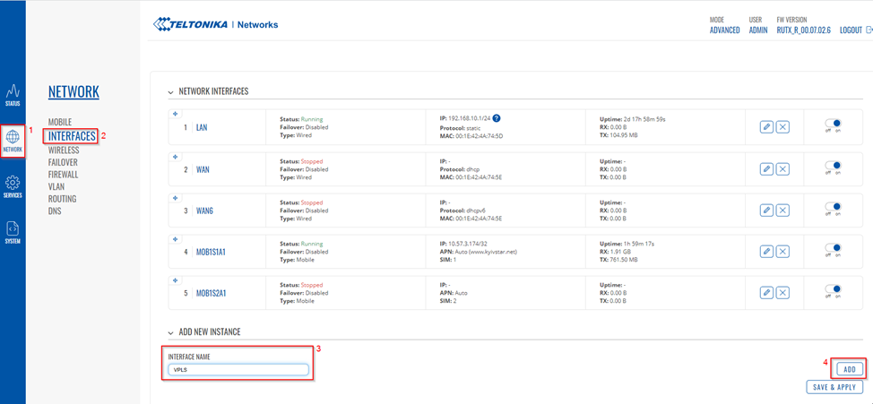
Go to Network > Interfaces WebUI section.
- Enter new Interface Name.
- Click on Add button.
After doing that you will be redirected to new window to set up new interface, when there:
- Choose Static Protocol from drop-down list.
- Press on Switch Protocol.
- Write IPv4 address to private address VPLS connections.
- Write IPv4 netmask to private address VPLS connections.
After switching protocol More setting options will appear:
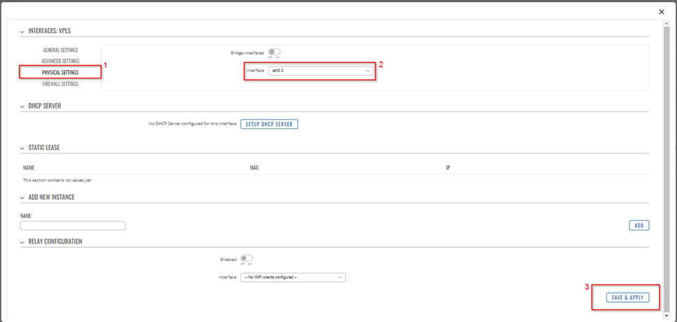
- Go to Physical Settings.
- From drop-down list choose previously created VLAN interface (in this example it is eth0.3)
- Press Apply & Save.
Check new VPLS interface
Insert VPLS cable in selected port, go to Network > Interfaces WebUI section and if you followed steps correctly yours newly created VPLS interface should be running and have an IP.

ZeroTier One VPN configuration RutOS
Wiki docks to ZeroTier VPN configuration
Configure General settings OSPF Protocol
Go to Network > Routing > Dynamik Routes > OSPF WebUI section.

- Enable OSPF instance on check bar.
- Enable VTY access from LAN ON.
- Generate a default external route from drop-down list, select Default, Default - Advertises the default route if the route is in the route table.
- Redistribution options, from drop-down list, select Connected. It redistribute connected network to another routers on same network.
Configure OSPF Interface
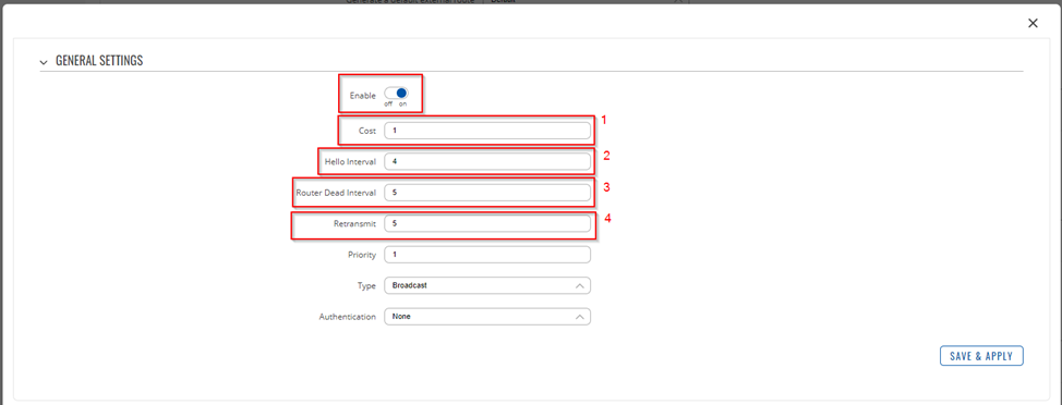
In this concept we need make priority on VPLS data channel, to minimize delay. [[File:OSPF via VPLS and ZerotierVPN OSPF Interface Temp.png]
- Add new OSPF interface.
- Change Name Interface from drop-down list, select VPLS interface.
- Enable OSPF Interface on check bar.
- Press Edit and state Cost, Hello Interval, Router Dead Interval and Retransmit.
- Press Save & Apply.
Configure OSPF Area
Create OSPF Area, and configure him number.

Configure OSPF Networks

Add 2 new instance with VPLS and Zerotier subnet for broadcast OSPF flags on this networks.
After that press Save & Apply.
Checking the functionality of the architecture
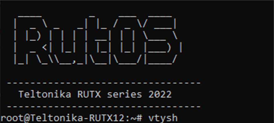
Connect to device via SSH and press command “vtysh”
Check OSPF neighbor device with command “show ip ospf neighbor”
The figure above shows all the neighbors that we managed to contact via OSPF, as we can see, routers with addresses 10.0.0.2, 10.0.0.3 and 10.0.0.4 neighbor on the eth0.3 interface, that is, the VPLS interface.
While the routers are 172.23.0.10, 172.23.0.30, 172.23.0.50 via the ztbto4jk6k interface, that is, via the Zerotier interface.
Check routes via command “show ip route”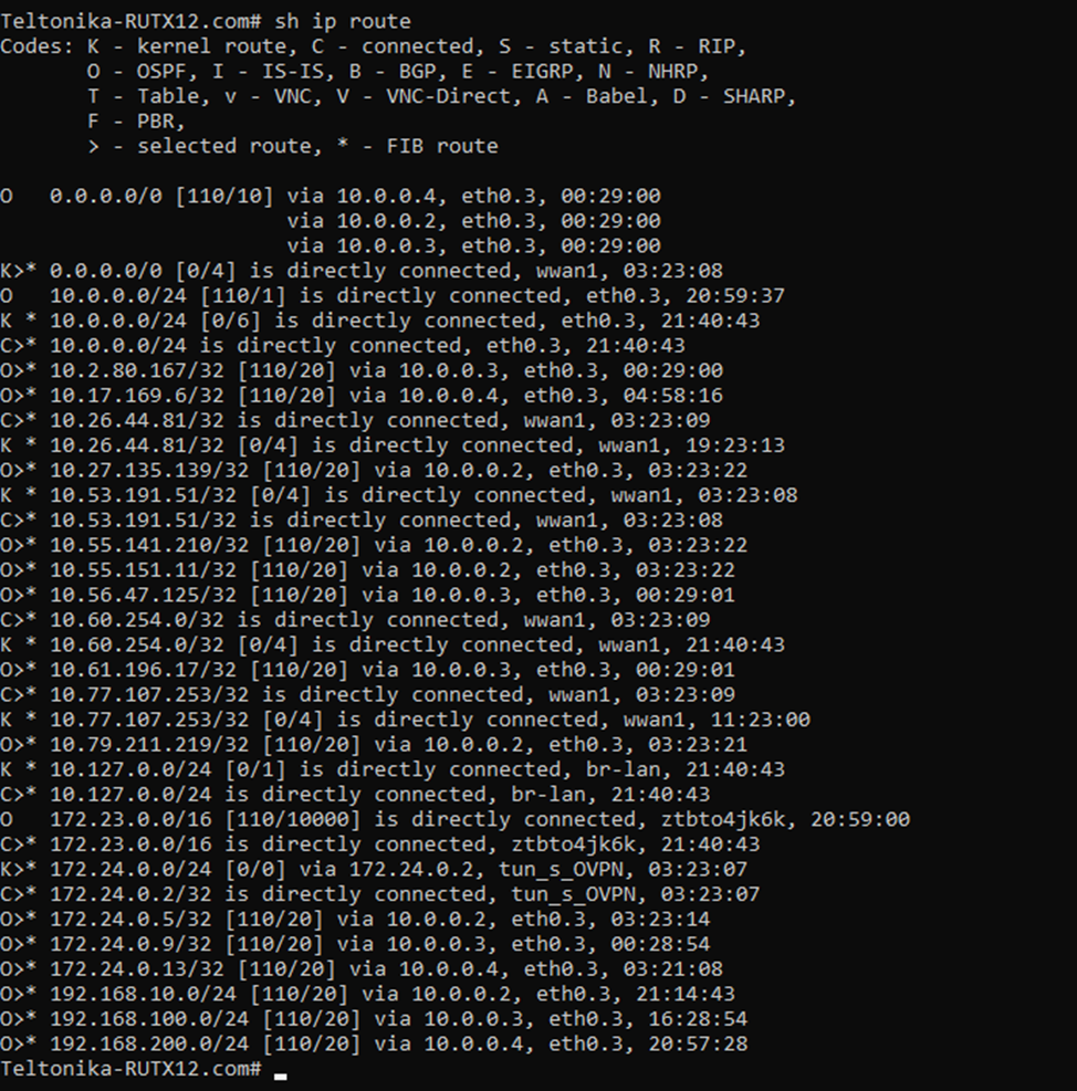
The figure below shows the routing table, according to which we can see that we have received routes from routers with which OSPF neighbors (192.168.10.0/24.192.168.100.0/24.192.168.200.0/24.)
We also received default routes (0.0.0.0/0) from the routers on the back side, which will allow us to have backup internet connections in case the LTE connection on the site drops.
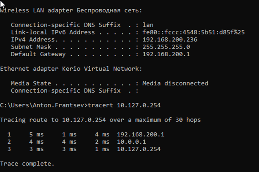
Finally route trace test. Connect client(you notebook) to router, and get address via DHCP, in test we see what computer get address 192.168.200.236 and we make tracert to server with another addresses ( 10.127.0.254 )
If we make trace we see all hops, Gateway 192.168.200.1 on side 192.168.200.1, VPLS interface routers on side 10.127.0.1/24 and last hop its endpoint (10.127.0.254)


