Data transfer from Modbus TCP to Modbus RTU Gateway
Summary
A functionality that allows to forward data from Modbus TCP to Modbus RTU is called Modbus gateway. This configuration example will be based on RUT955.
Modbus RTU means that the Modbus protocol is used on top of a serial RS232 or RS485 interface connection, meanwhile Modbus TCP is used over the network. In this configuration example we will show you how to transmit data between these connections. To understand the setup better, here is connection topology:
topology.png
Here you can see that the Slave device is connected to the Serial port and Master is connected to LAN port and it sends it's commands through TCP.
Configuring the router
Follow these steps to set up the Modbus gateway:
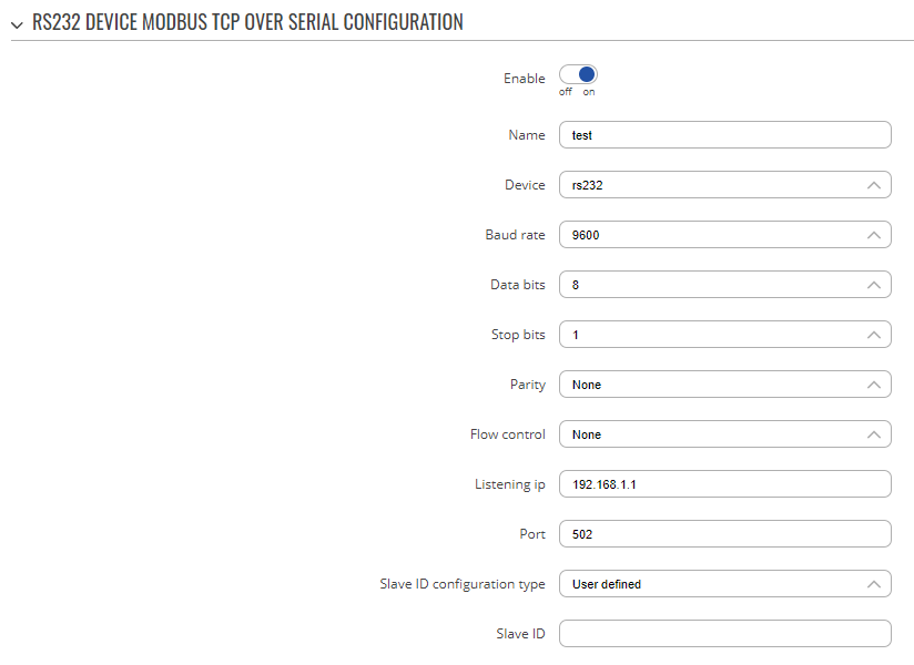
- Navigate to Services -> RS232 or RS485 (depending on your serial interface choice).
- In the configuration section, press Enable to enable the serial interface.
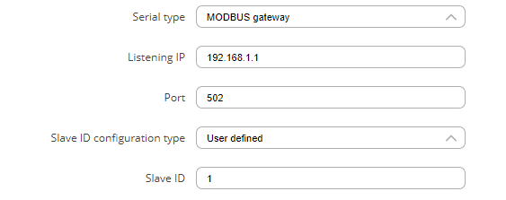
- In the Serial Type section, select Modbus gateway.
You may need to change configuration depending on your needs, just make sure that identical settings are set here and in RTU simulator: Baud rate, data bits, parity, stop bits, flow control.
This will expand more customization options:
- Listening IP – IP interface on which you are listening for incoming connections (input 0.0.0.0 to listen on any IP address).
- Port – Port number for Modbus gateway (default port is 502).
- Slave ID configuration type – User defined or obtained from TCP.
- Slave ID – preconfigured Slave ID number.
In IP filter options on the serial configuration page, add IP addresses that will be allowed to reach your Modbus gateway (input 0.0.0.0/0 to allow any IP address).
After finishing the configuration, press Save & Apply. With a setup like this, you will be able to send data from Modbus TCP to Modbus RTU.
TCP and RTU application setup
To test out this functionality you can use two PCs: one running a Modbus Master simulator and the other running a Modbus PLC simulator, acting as a Modbus slave. Follow these steps to configure this testing scenario:
- Connect PC1 to RUT955 RS232 port.
- Connect PC2 to RUT955 Ethernet LAN port.
Modbus RTU setup:
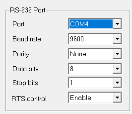
- On PC1, run the ModRSsim2 application.
- In the Prot: section select Modbus RS-232.
- In the menu in the top right corner, select Setup communication Serial or TCP/IP port.
- Enter the COM port on which the device is connected. Set the Baud rate to be the same as in the RUT955 serial settings. Click on RTS control and select disable (if flow control in RUT955 settings is set to none).
After completing these steps, the Modbus RTU configuration is finished.
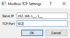
- On the PC2, run the QModMaster application.
- Select Modbus Mode: TCP.
- Navigate to Options -> Modbus TCP settings to configure TCP connection. Input Slave IP and TCP Port.
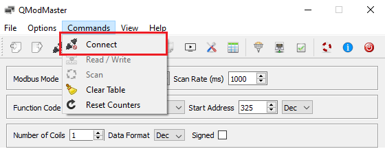
- To establish connection navigate to Commands -> Connect.
With that, the Modbus TCP configuration is finished.
Testing the configuration
To test the configuration, we could try to change some values in the Modbus PLC simulator and then try to read them via Modbus Master application. You might need to disable Firewall in both PC1 and PC2, or modify Firewall rules to allow both applications through the Firewall.
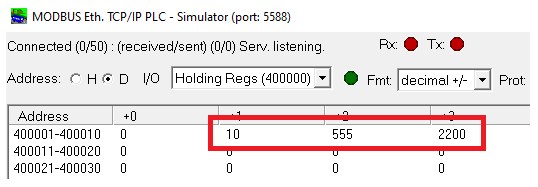
First of all, let's change Holding registers data in Modbus PLC:
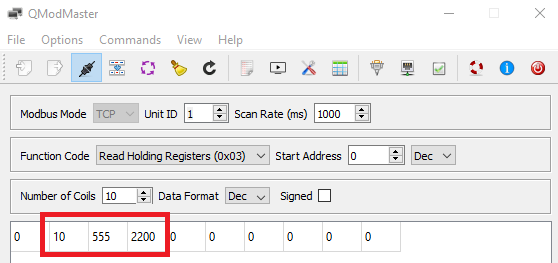
Then using Function code Read Holding Registers, try to read the data from the PLC simulator. To read data, navigate to Commands -> Read / Write.
If the data is displayed correctly, congratulations, the configuration works! If not, I advise to follow these steps once again.

