Difference between revisions of "Template:Networking rutos manual input output"
(prepare for release) |
(fixes) |
||
| Line 1: | Line 1: | ||
{{Template:Networking_rutos_manual_fw_disclosure | {{Template:Networking_rutos_manual_fw_disclosure | ||
| − | | fw_version = | + | | fw_version = TRB1_R_00.02.03 |
| − | | series = | + | | series = TRB1 |
}} | }} | ||
| Line 8: | Line 8: | ||
==Summary== | ==Summary== | ||
| − | <b>Inputs</b> and <b>outputs</b> are used for monitoring and controlling a connected device or receiving signals from that device in order to trigger certain events. This chapter is an overview of the Input/Output section for | + | <b>Inputs</b> and <b>outputs</b> are used for monitoring and controlling a connected device or receiving signals from that device in order to trigger certain events. This chapter is an overview of the Input/Output section for TRB141 devices. |
{{Template:Networking_rutos_manual_basic_advanced_webui_disclaimer}} | {{Template:Networking_rutos_manual_basic_advanced_webui_disclaimer}} | ||
| − | {{#switch: | + | {{#switch:TRB1 |
| RUTX = | | RUTX = | ||
==Characteristics== | ==Characteristics== | ||
| Line 31: | Line 31: | ||
</ul> | </ul> | ||
| TRB1 = | | TRB1 = | ||
| − | {{#ifeq: | + | {{#ifeq:TRB141|TRB141 |
| | | | ||
==Characteristics== | ==Characteristics== | ||
| Line 38: | Line 38: | ||
===Power Socket Pins=== | ===Power Socket Pins=== | ||
| − | ---- | + | ----[[File:Networking_trb141_manual_I-O_power_v1.png|border|class=tlt-border|353x353px]]<br /> |
| − | [[File:Networking_trb141_manual_I-O_power_v1.png|border|class=tlt-border|353x353px]]<br /> | ||
*'''Power''' pin: +9 ... +30 VDC positive power input. | *'''Power''' pin: +9 ... +30 VDC positive power input. | ||
*'''Ground''' pin: negative/ground connection from power supply. | *'''Ground''' pin: negative/ground connection from power supply. | ||
*'''I/0''' pins: programmable Input/Output pins (Open Collector output, max 30V or Digital input where 0-7.3 V is detected as logical "0", 7.3-30 V is detected as logical "1"). | *'''I/0''' pins: programmable Input/Output pins (Open Collector output, max 30V or Digital input where 0-7.3 V is detected as logical "0", 7.3-30 V is detected as logical "1"). | ||
| − | |||
| − | |||
| − | + | ===Connector Pins=== | |
---- | ---- | ||
| − | + | [[File:Networking_trb141_manual_I-O_socket_v1.png|345x345px|border|class=tlt-border]] | |
| − | < | + | *'''DI1''' and '''DI2''' are DRY/WET configurable inputs. WET: 0-1.9 V is detected as logical "0", 1.9-3.8 V is detected as logical "1". DRY: Logical "0" is detected when input is shorted to GND, otherwise input is detected as logical "1". |
| − | + | *'''NC<sub>1</sub> C<sub>1</sub>''' and '''NO<sub>1</sub>''' are respectively Normally Closed, Common and Normally Open contacts of internal Non-Latching Relay. Maximum relay ratings: 0.5A at 60 VDC/70 VAC, 1A at 30 VDC/VAC. | |
| − | + | *'''NC<sub>2</sub> C<sub>2</sub>''' and '''NO<sub>2</sub>''' are respectively Normally Closed, Common and Normally Open contacts of internal Latching Relay. Maximum relay ratings: 0.8A at 70 VDC, 0.9A at 70 VAC, 2A at 30 VDC/VAC. | |
| − | + | *'''A''' is ADC input. Analog voltage range 0 - 30 V. Input can be configured for 4-20mA sensor protocol as current measurement of 0 - 30 mA. | |
| − | + | *'''l''' and '''⏚''' are isolated input contacts. 0-7.3 V is detected as logical "0", 7.3-71 V is detected as logical "1". | |
| − | + | *'''+''' is power output connected directly to gateway's power supply input pin. This Output can be used for powering external 4-20 mA current sensor. | |
| − | + | *'''3.8''' is 3.8V power output which can be used to power 1-Wire sensors when needed. | |
| − | + | *'''1W''' 1-Wire protocol input/output. | |
| − | + | *'''⏚''' is GND contact. | |
}} | }} | ||
| TRB2 = | | TRB2 = | ||
| Line 68: | Line 65: | ||
==Status== | ==Status== | ||
| − | {{#switch: | + | {{#switch:TRB1 |
| − | | | + | | TRB2 = |
| − | The <b>Status</b> page displays the current states of the device | + | The <b>Status</b> page displays the current states of the device configurable inputs and outputs: |
| − | [[File: | + | [[File:Networking_trb2_manual_input_output_status_v1.png|border|class=tlt-border]] |
| − | You can invert Input | + | You can invert Input pins by clicking on clider in <b>Inversion</b> column and switch Outputs pin state by clicking on slider in <b>State</b> column. |
===Status from command line=== | ===Status from command line=== | ||
---- | ---- | ||
| − | You can also obtain the status of the input or output from the command line. List of ubus possible <b>values</b> in | + | You can also obtain the status of the input or output from the command line. List of ubus possible <b>values</b> in TRB141 devices: |
| − | ioman.gpio. | + | ioman.adc.adc0 |
| − | ioman.gpio. | + | ioman.gpio.dio0 |
| + | ioman.gpio.dio1 | ||
| + | ioman.gpio.dio2 | ||
Call command <b>ubus call <u>value</u> status </b>: | Call command <b>ubus call <u>value</u> status </b>: | ||
| − | root@Teltonika- | + | root@Teltonika-TRB141:~# ubus call ioman.gpio.dio0 status |
{ | { | ||
"value": "0", | "value": "0", | ||
| − | "direction": " | + | "direction": "out", |
| − | "bi_dir": | + | "bi_dir": true, |
"invert_input": false | "invert_input": false | ||
} | } | ||
<ul> | <ul> | ||
| − | <li><b> | + | <li><b>dio0</b> is configurable input / output: |
<ul> | <ul> | ||
<li>"value": "<b>0</b>" means low level state.</li> | <li>"value": "<b>0</b>" means low level state.</li> | ||
| Line 99: | Line 98: | ||
</ul> | </ul> | ||
</li> | </li> | ||
| − | <li><b> | + | <li><b>adc0</b> is analog input: |
<ul> | <ul> | ||
| − | <li>"value": "<b>0</b>" means | + | <li>"value": "<b>0.54</b>" means 0.54V.</li> |
| − | |||
</ul> | </ul> | ||
</li> | </li> | ||
</ul> | </ul> | ||
| − | | | + | | TRB1 = |
| + | {{#ifeq:TRB141|TRB141 | ||
| + | | | ||
The <b>Status</b> page displays the current states of the device configurable inputs and outputs: | The <b>Status</b> page displays the current states of the device configurable inputs and outputs: | ||
| − | [[File: | + | [[File:Networking_trb1_manual_input_output_status_v1.png|border|class=tlt-border]] |
You can invert Input pins by clicking on clider in <b>Inversion</b> column and switch Outputs pin state by clicking on slider in <b>State</b> column. | You can invert Input pins by clicking on clider in <b>Inversion</b> column and switch Outputs pin state by clicking on slider in <b>State</b> column. | ||
| Line 115: | Line 115: | ||
===Status from command line=== | ===Status from command line=== | ||
---- | ---- | ||
| − | You can also obtain the status of the input or output from the command line. List of ubus possible <b>values</b> in | + | You can also obtain the status of the input or output from the command line. List of ubus possible <b>values</b> in TRB141 devices: |
| + | ioman.acl.acl0 | ||
ioman.adc.adc0 | ioman.adc.adc0 | ||
| + | ioman.dwi.dwi0 | ||
| + | ioman.dwi.dwi1 | ||
ioman.gpio.dio0 | ioman.gpio.dio0 | ||
ioman.gpio.dio1 | ioman.gpio.dio1 | ||
| − | ioman.gpio. | + | ioman.gpio.iio |
| + | ioman.gpio.onewire | ||
| + | ioman.relay.relay0 | ||
| + | ioman.relay.relay1 | ||
| + | |||
| + | In order to read value use '''''status''''' command. | ||
| + | |||
| + | ubus call ioman.gpio.dio0 status | ||
| + | ubus call ioman.relay.relay0 status | ||
| + | |||
| + | To change input settings use '''''update''''' command and write the value. | ||
| + | |||
| + | ubus call ioman.gpio.dio0 update '{"value":"0"}' | ||
| + | ubus call ioman.gpio.dio0 update '{"value":"1"}' | ||
| + | |||
| + | To change relay settings use '''''update''''' command and write state. | ||
| + | |||
| + | ubus call ioman.relay.relay0 update '{"state":"open"}' | ||
| + | ubus call ioman.relay.relay0 update '{"state":"closed"}' | ||
| + | |||
| + | ===Reading I/O values from directory=== | ||
| + | ---- | ||
| + | |||
| + | You can also collect I/O values straight from directories in your device. | ||
| + | |||
| + | ====Digital inputs, Relay outputs==== | ||
| + | ---- | ||
| + | |||
| + | Following is a list of I/O directories in '''''/sys/class/gpio/''''': | ||
| + | |||
| + | dwi1(dry wet) input 14; toggle 12 (to read value refer to gpio14, to change state dry/wet refer to gpio12) | ||
| + | dwi2(dry wet) input 15; toggle 38 (to read value refer to gpio15, to change state dry/wet refer to gpio38) | ||
| + | relay open 20; closed 22; (turn off gpio20 set to 0, turn on gpio22 set value to 1; and visa versa) | ||
| + | latching relay open 23; close 21 (turn off gpio23 set to 0, turn on gpio21 set value to 1; and visa versa) | ||
| + | dio0 (power socket) input 13; output 16 (direction can be changed, to read input use gpio13, to control output use gpio16) | ||
| + | dio1 (power socket) input 17; output 78 (direction can be changed, to read input use gpio17, to control output use gpio78) | ||
| + | iio (isolated input) input 1021 (to read value refer to gpio1021) | ||
| + | |||
| + | In order to read digital input value use '''''cat''''' command. | ||
| + | |||
| + | cat /sys/class/gpio/gpio14/value | ||
| + | cat /sys/class/gpio/gpio15/value | ||
| + | cat /sys/class/gpio/gpio1021/value | ||
| + | |||
| + | To change input state use '''''echo''''' command where "1" is "dry" state and "0" is "wet" state. | ||
| + | |||
| + | echo 0 > /sys/class/gpio/gpio12/value | ||
| + | echo 1 > /sys/class/gpio/gpio38/value | ||
| + | |||
| + | When one Relay output is open, other one is closed, so turning on/off the output you will have to change value on both pins. For that '''''echo''''' command is used. Same principle applies to Latching Relay output. | ||
| + | |||
| + | echo 1 > /sys/class/gpio/gpio20/value & echo 0 > /sys/class/gpio/gpio22/value | ||
| + | echo 1 > /sys/class/gpio/gpio23/value & echo 0 > /sys/class/gpio/gpio21/value | ||
| + | |||
| + | ====ADC (Analog Input)==== | ||
| + | ---- | ||
| + | |||
| + | ADC (Analog input) can be read from different directory, '''''/sys/devices/qpnp-vadc-8/mpp4_vadc''''' also using '''''cat''''' command, but received Result value has to be divided by 126582 to get number in volts. | ||
| + | |||
| + | cat /sys/devices/qpnp-vadc-8/mpp4_vadc | ||
| + | | <!-- for other TRB1 --> | ||
| + | The <b>Status</b> page displays the current states of the device input and output: | ||
| + | |||
| + | [[File:Networking_rutx_manual_input_output_status_v2.png|border|class=tlt-border]] | ||
| + | |||
| + | You can invert Input pin by clicking on clider in <b>Inversion</b> column and switch Output pin state by clicking on slider in <b>State</b> column. | ||
| + | |||
| + | ===Status from command line=== | ||
| + | ---- | ||
| + | You can also obtain the status of the input or output from the command line. List of ubus possible <b>values</b> in TRB141 devices: | ||
| + | |||
| + | ioman.gpio.din1 | ||
| + | ioman.gpio.dout1 | ||
Call command <b>ubus call <u>value</u> status </b>: | Call command <b>ubus call <u>value</u> status </b>: | ||
| − | root@Teltonika- | + | root@Teltonika-TRB141:~# ubus call ioman.gpio.dout1 status |
{ | { | ||
"value": "0", | "value": "0", | ||
| − | "direction": " | + | "direction": "in", |
| − | "bi_dir": | + | "bi_dir": false, |
"invert_input": false | "invert_input": false | ||
} | } | ||
<ul> | <ul> | ||
| − | <li><b> | + | <li><b>din1</b> is the input: |
<ul> | <ul> | ||
<li>"value": "<b>0</b>" means low level state.</li> | <li>"value": "<b>0</b>" means low level state.</li> | ||
| Line 138: | Line 213: | ||
</ul> | </ul> | ||
</li> | </li> | ||
| − | <li><b> | + | <li><b>dout1</b> is the output: |
<ul> | <ul> | ||
| − | <li>"value": "<b>0. | + | <li>"value": "<b>0</b>" means low level state.</li> |
| + | <li>"value": "<b>1</b>" means high level state.</li> | ||
</ul> | </ul> | ||
</li> | </li> | ||
</ul> | </ul> | ||
| − | | | + | }} |
| − | The <b>Status</b> page displays the current states of the device | + | | <!-- for rutx --> |
| + | The <b>Status</b> page displays the current states of the device input and output: | ||
| − | [[File: | + | [[File:Networking_rutx_manual_input_output_status_v2.png|border|class=tlt-border]] |
| − | You can invert Input | + | You can invert Input pin by clicking on clider in <b>Inversion</b> column and switch Output pin state by clicking on slider in <b>State</b> column. |
===Status from command line=== | ===Status from command line=== | ||
---- | ---- | ||
| − | You can also obtain the status of the input or output from the command line. List of ubus possible <b>values</b> in | + | You can also obtain the status of the input or output from the command line. List of ubus possible <b>values</b> in TRB141 devices: |
| − | + | ioman.gpio.din1 | |
| − | + | ioman.gpio.dout1 | |
| − | |||
| − | |||
| − | |||
| − | ioman.gpio. | ||
| − | ioman.gpio. | ||
| − | |||
| − | |||
| − | |||
Call command <b>ubus call <u>value</u> status </b>: | Call command <b>ubus call <u>value</u> status </b>: | ||
| − | root@Teltonika- | + | root@Teltonika-TRB141:~# ubus call ioman.gpio.dout1 status |
{ | { | ||
"value": "0", | "value": "0", | ||
| − | "direction": " | + | "direction": "in", |
| − | "bi_dir": | + | "bi_dir": false, |
"invert_input": false | "invert_input": false | ||
} | } | ||
| − | + | <ul> | |
| + | <li><b>din1</b> is the input: | ||
| + | <ul> | ||
| + | <li>"value": "<b>0</b>" means low level state.</li> | ||
| + | <li>"value": "<b>1</b>" means high level state.</li> | ||
| + | </ul> | ||
| + | </li> | ||
| + | <li><b>dout1</b> is the output: | ||
| + | <ul> | ||
| + | <li>"value": "<b>0</b>" means low level state.</li> | ||
| + | <li>"value": "<b>1</b>" means high level state.</li> | ||
| + | </ul> | ||
| + | </li> | ||
| + | </ul> | ||
| + | }} | ||
| Line 278: | Line 361: | ||
The figure below is an example of Conditions section. | The figure below is an example of Conditions section. | ||
| − | {{#switch: | + | {{#switch:TRB1 |
| TRB1 = [[File:Networking_trb1_manual_input_output_iojuggler_general_v1.png]] | | TRB1 = [[File:Networking_trb1_manual_input_output_iojuggler_general_v1.png]] | ||
| TRB2 = [[File:Networking_trb2_manual_input_output_iojuggler_general_v1.png]] | | TRB2 = [[File:Networking_trb2_manual_input_output_iojuggler_general_v1.png]] | ||
| Line 560: | Line 643: | ||
<td>string; default: <b>none</b></td> | <td>string; default: <b>none</b></td> | ||
<td>Parameters and their value from device for usage in Post or Get requests. | <td>Parameters and their value from device for usage in Post or Get requests. | ||
| − | {{#switch: | + | {{#switch:TRB141 |
| RUTX10 = Possible values: Time stamp, UNIX time, WAN MAC, Wired WAN IP, Network info, Product code, LAN MAC address, LAN IP address, Serial number, Current FW version, Monitoring status, Input Name, Input state change trigger </td> | | RUTX10 = Possible values: Time stamp, UNIX time, WAN MAC, Wired WAN IP, Network info, Product code, LAN MAC address, LAN IP address, Serial number, Current FW version, Monitoring status, Input Name, Input state change trigger </td> | ||
| RUTX08 = Possible values: Time stamp, UNIX time, WAN MAC, Wired WAN IP, Network info, Product code, LAN MAC address, LAN IP address, Serial number, Current FW version, Monitoring status, Input Name, Input state change trigger </td> | | RUTX08 = Possible values: Time stamp, UNIX time, WAN MAC, Wired WAN IP, Network info, Product code, LAN MAC address, LAN IP address, Serial number, Current FW version, Monitoring status, Input Name, Input state change trigger </td> | ||
| Line 646: | Line 729: | ||
{{#ifeq:{{{mobile}}}|0|| | {{#ifeq:{{{mobile}}}|0|| | ||
| − | {{#ifeq: | + | {{#ifeq:TRB1|TRB1|| |
=====Change sim===== | =====Change sim===== | ||
---- | ---- | ||
| Line 753: | Line 836: | ||
| − | {{#ifeq: | + | {{#ifeq:TRB1|RUTX|| |
=====Analog voltage===== | =====Analog voltage===== | ||
---- | ---- | ||
| Line 995: | Line 1,078: | ||
</table> | </table> | ||
| − | [[Category: | + | [[Category:TRB141 Services section]] |
Revision as of 08:42, 8 May 2020
Template:Networking rutos manual fw disclosure
Summary
Inputs and outputs are used for monitoring and controlling a connected device or receiving signals from that device in order to trigger certain events. This chapter is an overview of the Input/Output section for TRB141 devices. If you're having trouble finding this page or some of the parameters described here on your device's WebUI, you should turn on "Advanced WebUI" mode. You can do that by clicking the "Advanced" button, located at the top of the WebUI.
Characteristics
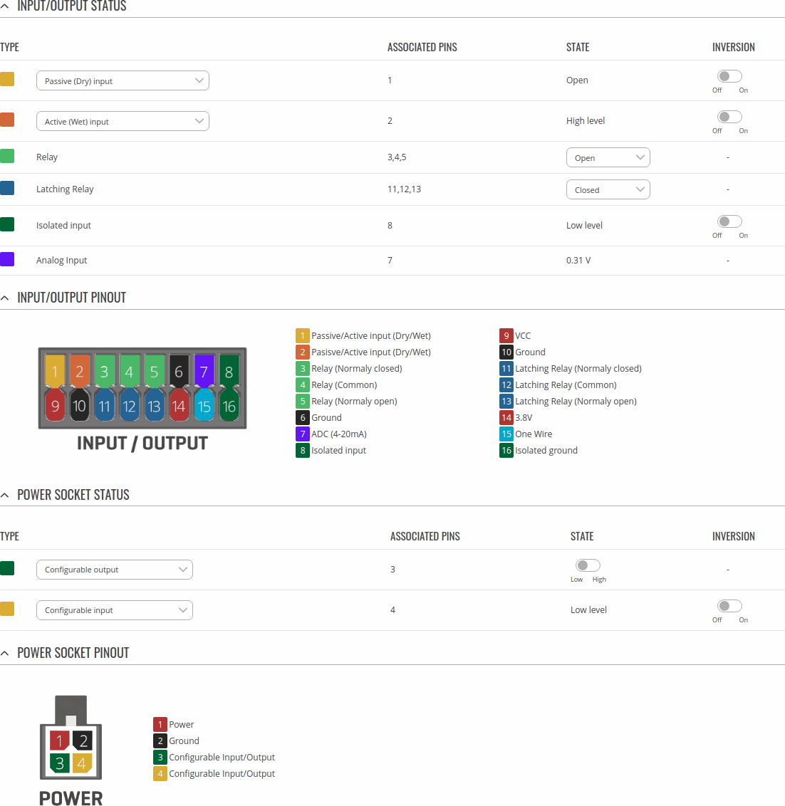
TRB141 has eighteen input/output pins, two of them can be found inside the power socket and the rest sixteen are on the side of the device. A list of Input/Output electric characteristics inherent in TRB141 devices can be found bellow.
Power Socket Pins
- Power pin: +9 ... +30 VDC positive power input.
- Ground pin: negative/ground connection from power supply.
- I/0 pins: programmable Input/Output pins (Open Collector output, max 30V or Digital input where 0-7.3 V is detected as logical "0", 7.3-30 V is detected as logical "1").
Connector Pins
- DI1 and DI2 are DRY/WET configurable inputs. WET: 0-1.9 V is detected as logical "0", 1.9-3.8 V is detected as logical "1". DRY: Logical "0" is detected when input is shorted to GND, otherwise input is detected as logical "1".
- NC1 C1 and NO1 are respectively Normally Closed, Common and Normally Open contacts of internal Non-Latching Relay. Maximum relay ratings: 0.5A at 60 VDC/70 VAC, 1A at 30 VDC/VAC.
- NC2 C2 and NO2 are respectively Normally Closed, Common and Normally Open contacts of internal Latching Relay. Maximum relay ratings: 0.8A at 70 VDC, 0.9A at 70 VAC, 2A at 30 VDC/VAC.
- A is ADC input. Analog voltage range 0 - 30 V. Input can be configured for 4-20mA sensor protocol as current measurement of 0 - 30 mA.
- l and ⏚ are isolated input contacts. 0-7.3 V is detected as logical "0", 7.3-71 V is detected as logical "1".
- + is power output connected directly to gateway's power supply input pin. This Output can be used for powering external 4-20 mA current sensor.
- 3.8 is 3.8V power output which can be used to power 1-Wire sensors when needed.
- 1W 1-Wire protocol input/output.
- ⏚ is GND contact.
Status
The Status page displays the current states of the device configurable inputs and outputs:
You can invert Input pins by clicking on clider in Inversion column and switch Outputs pin state by clicking on slider in State column.
Status from command line
You can also obtain the status of the input or output from the command line. List of ubus possible values in TRB141 devices:
ioman.acl.acl0
ioman.adc.adc0
ioman.dwi.dwi0
ioman.dwi.dwi1
ioman.gpio.dio0
ioman.gpio.dio1
ioman.gpio.iio
ioman.gpio.onewire
ioman.relay.relay0
ioman.relay.relay1
In order to read value use status command.
ubus call ioman.gpio.dio0 status
ubus call ioman.relay.relay0 status
To change input settings use update command and write the value.
ubus call ioman.gpio.dio0 update '{"value":"0"}'
ubus call ioman.gpio.dio0 update '{"value":"1"}'
To change relay settings use update command and write state.
ubus call ioman.relay.relay0 update '{"state":"open"}'
ubus call ioman.relay.relay0 update '{"state":"closed"}'
Reading I/O values from directory
You can also collect I/O values straight from directories in your device.
Digital inputs, Relay outputs
Following is a list of I/O directories in /sys/class/gpio/:
dwi1(dry wet) input 14; toggle 12 (to read value refer to gpio14, to change state dry/wet refer to gpio12)
dwi2(dry wet) input 15; toggle 38 (to read value refer to gpio15, to change state dry/wet refer to gpio38)
relay open 20; closed 22; (turn off gpio20 set to 0, turn on gpio22 set value to 1; and visa versa)
latching relay open 23; close 21 (turn off gpio23 set to 0, turn on gpio21 set value to 1; and visa versa)
dio0 (power socket) input 13; output 16 (direction can be changed, to read input use gpio13, to control output use gpio16)
dio1 (power socket) input 17; output 78 (direction can be changed, to read input use gpio17, to control output use gpio78)
iio (isolated input) input 1021 (to read value refer to gpio1021)
In order to read digital input value use cat command.
cat /sys/class/gpio/gpio14/value
cat /sys/class/gpio/gpio15/value
cat /sys/class/gpio/gpio1021/value
To change input state use echo command where "1" is "dry" state and "0" is "wet" state.
echo 0 > /sys/class/gpio/gpio12/value
echo 1 > /sys/class/gpio/gpio38/value
When one Relay output is open, other one is closed, so turning on/off the output you will have to change value on both pins. For that echo command is used. Same principle applies to Latching Relay output.
echo 1 > /sys/class/gpio/gpio20/value & echo 0 > /sys/class/gpio/gpio22/value
echo 1 > /sys/class/gpio/gpio23/value & echo 0 > /sys/class/gpio/gpio21/value
ADC (Analog Input)
ADC (Analog input) can be read from different directory, /sys/devices/qpnp-vadc-8/mpp4_vadc also using cat command, but received Result value has to be divided by 126582 to get number in volts.
cat /sys/devices/qpnp-vadc-8/mpp4_vadc
Post/Get
Enabling Post/Get will allow you to send HTTP POST/GET requests to device which controls the state of the output. The figure below is an example of the Post/Get configuration section and the table below provides information on the fields contained in that section:
| Field | Value | Description |
|---|---|---|
| Enable | off | on; default: off | Turns Post/Get on or off. |
| Username | string; default: none | Username used for authentication in POST/GET queries. |
| Password | string; default: none | Password used for authentication in POST/GET queries. |
Post/Get examples
It is possible to turn the output on and off by using a valid HTTP POST/GET syntax. Use a web browser or any other compatible software to submit HTTP POST/GET strings to the device.
Below is a table containing syntax examples of this usage:
| Action | POST/GET URL |
|---|---|
| Turn Output state to high | http://192.168.1.1/cgi-bin/io_state?username=user1&password=user1&pin=dout1&state=on |
| Turn Output state to low after 5 seconds for 3 seconds | http://192.168.1.1/cgi-bin/io_state?username=user1&password=user1&pin=dout1&state=on&delay=5&time=3 |
Overview:
- 192.168.1.1 - device default LAN IP address; replace it in accordance with your own configuration.
- username - login name from Post/Get configuration.
- password- password from Post/Get configuration.
- state - turn Output on or off.
- delay - defines a delay (in seconds) after which the specified action will be performed.
- time - defines a window of time during which the action will take place. For instance, if you post an on action while specifying time=5, the output will turn on and stay on for 5 seconds before turning off.
Delay and time parameters can be used together. For example, if delay is 10, time is 5, action is on, then 10 seconds after the execution of the command, the output will switch to on (or stay in on state if it was already that way), then after 5 more seconds it will switch to off state. In this case the overall command execution time is 15 seconds.
Scheduler
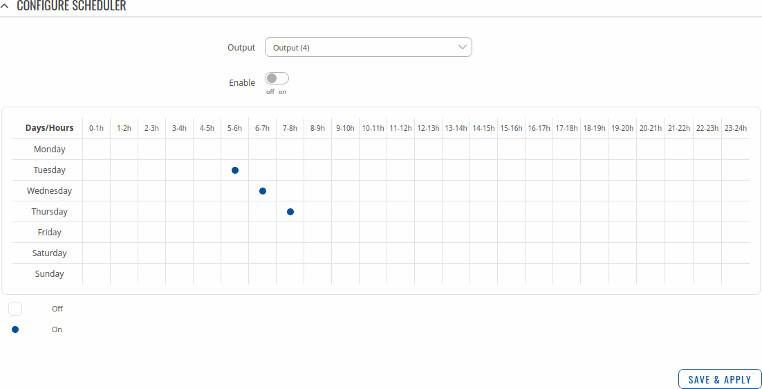
With the help of the output Scheduler you can configure a timetable of when the output should be enabled or disabled based on date and time. By default everything is unset.
Io juggler
The Io juggler page is used create automated actions based on Input state and conditions.
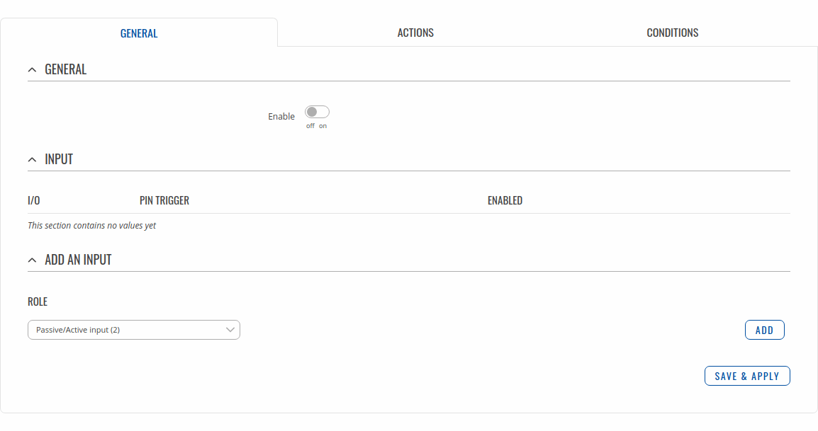
General
The General section allows you to create automated Actions based on selected Inputs and their trigger state. The figure below is an example of Conditions section.
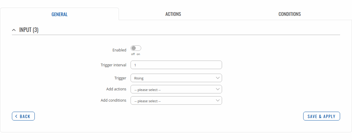
Modify Input configuration
You can find explanation about fields in the table below this illustration.
| Field | Value | Description |
|---|---|---|
| Enabled | off | on; default: off | Changes current profile to specified one when action triggers. |
| Trigger interval | positive integer; default: none | Specifies what is the shortest amount of seconds between triggers. |
| Trigger | Rising | Falling | Both; default: Rising | Specifies on which trigger state this rule will be activated. |
| Add actions | actions; default: none | Specifies actions which have to be met for rule to be executed. Actions are optional. |
| Add conditions | conditions; default: none | Specifies conditions which have to be met for action to occur. Conditions are optional. |
Actions
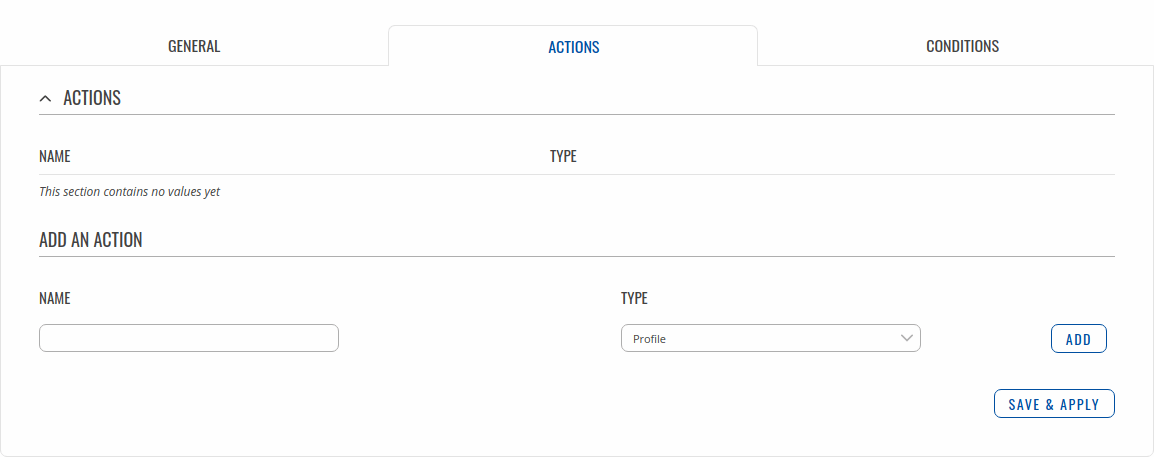
The Actions section lets you manage your created Actions for IO Juggler inputs. The figure below is an example of Actions section.
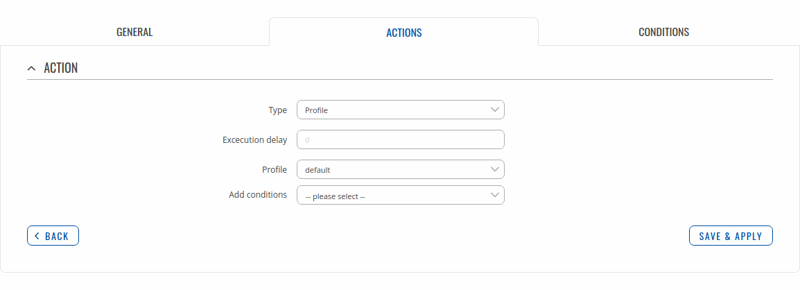
Modify action
Above is an example of what action configuration window looks like. Below is a table with detailed explanations on how to configure the action and what each of the fields mean. To avoid redundancy, screenshots for the other actions will not be provided, since the structures, syntax and the overall look of the configuration windows for each action are very similar. Instead, only tables containing information on how to edit each action will be provided.
Profile
| Field | Value | Description |
|---|---|---|
| Type | Profile | Changes current profile to specified one when action triggers. |
| Execution delay | positive integer; default: none | How many seconds will pass before the action is excecuted after it's triggered. |
| Profile | profile; default: default | Choose a profile that will be applied when the action triggers. |
| Add conditions | conditions; default: none | Specifies conditions which have to be met for action to occur. Conditions are optional. |
| Field | Value | Description |
|---|---|---|
| Type | Sends email when action triggers. | |
| Subject | string; default: none | Subject of email. |
| Text message | string; default: none | Text message to be sent in email. Below this field you can find device information and their codes, which can be included in messages to send device information. |
| Execution delay | positive integer; default: none | How many seconds will pass before the action is excecuted after it's triggered. |
| Email user | email user; default: none | Configured email user. |
| Recipient's email address | string; default: none | Email receiver(s). |
| Add conditions | conditions; default: none | Specifies conditions which have to be met for action to occur. Conditions are optional. |
SMS
| Field | Value | Description |
|---|---|---|
| Type | SMS | Sends sms when action triggers. |
| Text message | string; default: none | Text message to be sent in sms. Below this field you can find device information and their codes, which can be included in messages to send device information. |
| Execution delay | positive integer; default: none | How many seconds will pass before the action is excecuted after it's triggered. |
| Recipients | Single number | Group; default: Single number | How many recipients will get the message. |
| Recipient's phone number | number; default: none | SMS receiver. |
| Phone group | phone group; default: none | SMS receivers. |
| Add conditions | conditions; default: none | Specifies conditions which have to be met for action to occur. Conditions are optional. |
Output
| Field | Value | Description |
|---|---|---|
| Type | Output | Changes Output state when action triggers. |
| Execution delay | positive integer; default: none | How many seconds will pass before the action is excecuted after it's triggered. |
| Control | output/relay; default: Output(4) | Specifies the output/relay of which the state will be changed. |
| Revert | integer; default: 0 | After how many seconds the state will revert. If left 0 or empty the state will not revert. |
| Maintain | off | on; default: on | Maintain this IO state after reboot. |
| Invert | off | on; default: off | On action inverts pin state. |
| State copying | off | on; default: off | Copies the state from selected input to selected output. |
| State | High | Low; default: High | Specifies what state the output pin will be set to. |
| Add conditions | conditions; default: none | Specifies conditions which have to be met for action to occur. Conditions are optional. |
HTTP
| Field | Value | Description |
|---|---|---|
| Type | HTTP | Sends HTTP request when action triggers. |
| Execution delay | positive integer; default: none | How many seconds will pass before the action is excecuted after it's triggered. |
| Method | Get | Post; default: Get | Specifies the output/relay of which the state will be changed. |
| URL | string; default: none | URL to send request to. |
| Verify | off | on; default: off | Verifies the validity of certificates, only works for https. |
| Parameters | string; default: none | Parameters and their value from device for usage in Post or Get requests. Possible values: Time stamp, UNIX time, WAN MAC, Wired WAN IP, Network info, Product code, LAN MAC address, LAN IP address, Serial number, Current FW version, Monitoring status, Input Name, Input state change trigger, RSCP, ECIO, SIM slot in use, CELLID, RSRQ, SINR, RSRP, SIM State, SIM pin state, Modem model, IMSI, Modem serial number , Network State, Data connection state, Connection type, Mobile IP, Operator name, Signal strenght, IMEI, ICCID, Neighbour cells, Network serving. |
| Add conditions | conditions; default: none | Specifies conditions which have to be met for action to occur. Conditions are optional. |
Script
| Field | Value | Description |
|---|---|---|
| Type | Script | Runs script when action triggers. |
| Execution delay | positive integer; default: none | How many seconds will pass before the action is excecuted after it's triggered. |
| Specify path | Upload a script | Specify path; default: Upload a cript | Selection to upload a script or specify its absolute path in device. |
| Custom script | -(interactive button) | Shows file upload window on click. |
| Script file | string; default: none | Absolute path to script file in device. |
| Arguments | string; default: none | Optional arguments which can be provided for the script. You can include device information with values given below this input field. |
| Add conditions | conditions; default: none | Specifies conditions which have to be met for action to occur. Conditions are optional. |
Reboot
| Field | Value | Description |
|---|---|---|
| Type | Reboot | Reboots device when action triggers. |
| Execution delay | positive integer; default: none | How many seconds will pass before the action is excecuted after it's triggered. |
| Add conditions | conditions; default: none | Specifies conditions which have to be met for action to occur. Conditions are optional. |
Conditions
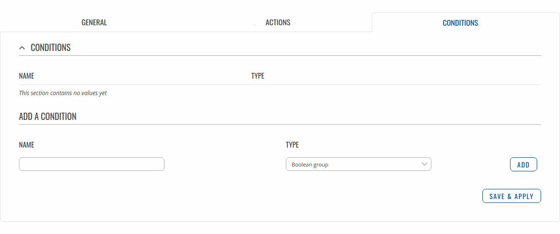
The Conditions section lets you manage your created Conditions for IO Juggler Actions. The figure below is an example of Conditions section.
Modify condition
Above is an example of what condition configuration window looks like. Below is a table with detailed explanations on how to configure the condition and what each of the fields mean. To avoid redundancy, screenshots for the other conditions will not be provided, since the structures, syntax and the overall look of the configuration windows for each condition are very similar. Instead, only tables containing information on how to edit each condition will be provided.
Boolean group
| Field | Value | Description |
|---|---|---|
| Condition type | Boolean group | A type of condition. |
| Boolean type | AND | NAND | OR | NOR; default: AND | Type of boolean condition. |
| Add conditions | conditions; default: none | Specifies conditions which have to be met for action to occur. Conditions are optional. |
I/O
| Field | Value | Description |
|---|---|---|
| Condition type | I/O | A type of condition. |
| I/O | inputs/outputs; default: Output(4) | Specifies the I/O to which the condition is listening to. |
| State | High | Low; default: High | Specifies in what state the pin has to be. |
Analog voltage
| Field | Value | Description |
|---|---|---|
| Condition type | Analog voltage | A type of condition. |
| Condition | Inside voltage | Outside voltage; default: Inside voltage | Whether to evaluate the condition as true inside or outside the specified range. |
| Input | inputs; default: none | Specifies the analog input to which the condition is listening to. |
| Min voltage | positive float; default: none | Specifies minimum voltage of range. |
| Max voltage | positive float; default: none | Specifies magimum voltage of range. |
Minute
| Field | Value | Description |
|---|---|---|
| Condition type | Minute | A type of condition. |
| Inverted function | off | on; default: off | Inverts the selected condition type. Makes the condition true if the time/date is outside the specified interval. |
| Interval | off | on; default: off | Switches between a specific value and a time interval. |
| Minute | integer [0..59]; default: none | Specifies minute at which the action can occur. |
| Start minute | integer [0..59]; default: none | Specifies starting minute of the interval at which the action can occur. |
| End minute | integer [0..59]; default: none | Specifies ending minute of the interval at which the action can occur. |
Hour
| Field | Value | Description |
|---|---|---|
| Condition type | Hour | A type of condition. |
| Inverted function | off | on; default: off | Inverts the selected condition type. Makes the condition true if the time/date is outside the specified interval. |
| Interval | off | on; default: off | Switches between a specific value and a time interval. |
| Hour | integer [0..59]; default: none | Specifies hour at which the action can occur. |
| Start hour | integer [0..59]; default: none | Specifies starting hour of the interval at which the action can occur. |
| End hour | integer [0..59]; default: none | Specifies ending hour of the interval at which the action can occur. |
Weekday
| Field | Value | Description |
|---|---|---|
| Condition type | Weekday | A type of condition. |
| Inverted function | off | on; default: off | Inverts the selected condition type. Makes the condition true if the time/date is outside the specified interval. |
| Interval | off | on; default: off | Switches between a specific value and a time interval. |
| Weekday | weekday; default: Monday | Specifies weekday at which the action can occur. |
| Start weekday | weekday; default: Monday | Specifies starting weekday of the interval at which the action can occur. |
| End weekday | weekday; default: Monday | Specifies ending weekday of the interval at which the action can occur. |
Month day
| Field | Value | Description |
|---|---|---|
| Condition type | Month day | A type of condition. |
| Month override | off | on; default: off | If the option is selected and the specified day is not in the month then the condition uses the last day of the month. |
| Interval | off | on; default: off | Switches between a specific value and a time interval. |
| Day of the month | integer [1..31]; default: none | Specifies day of the month at which the action can occur. |
| Start day of the month | integer [1..31]; default: none | Specifies starting day of the interval of the month at which the action can occur. |
| End day of the month | integer [1..31]; default: none | Specifies ending day of the interval of the month at which the action can occur. |
Year
| Field | Value | Description |
|---|---|---|
| Condition type | Year | A type of condition. |
| Inverted function | off | on; default: off | Inverts the selected condition type. Makes the condition true if the time/date is outside the specified interval. |
| Interval | off | on; default: off | Switches between a specific value and a time interval. |
| Day of the year | integer [1..366]; default: none | Specifies day of the year at which the action can occur. |
| Start day of the year | integer [1..366]; default: none | Specifies starting day of the interval of the year at which the action can occur. |
| End day of the year | integer [1..366]; default: none | Specifies ending day of the interval of the year at which the action can occur. |

