Difference between revisions of "Template:Networking trb145 manual rs485 pinout"
From Teltonika Networks Wiki
| Line 8: | Line 8: | ||
<td style="width: 100px;"><b>Name</b></td> | <td style="width: 100px;"><b>Name</b></td> | ||
<td><b>Description</b></td> | <td><b>Description</b></td> | ||
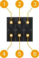
| − | <td style="border-bottom: 1px solid white;" rowspan=" | + | <td style="border-bottom: 1px solid white;" rowspan="8">[[File:Trb145 rs485 pinout v2.png|130px|right|bottom]]</td> |
</tr> | </tr> | ||
<tr> | <tr> | ||
| Line 39: | Line 39: | ||
<td>Vin</td> | <td>Vin</td> | ||
<td>Power input 9-30 VDC</td> | <td>Power input 9-30 VDC</td> | ||
| + | </tr> | ||
| + | <tr style="border-bottom: 1px solid white; color: white;"> | ||
| + | <td>.</td> | ||
| + | <td></td> | ||
| + | <td></td> | ||
</tr> | </tr> | ||
</table> | </table> | ||
