Difference between revisions of "TRB142 Front & Back Panels"
From Teltonika Networks Wiki
(Created page with "{{Template: Networking_device_manual_panels | name = TRB142 | series = TRB14x | file_front = Trb142_front_view_v2.png | size_front = 400 | file_back = Trb142_back_v...") |
|||
| (One intermediate revision by the same user not shown) | |||
| Line 1: | Line 1: | ||
{{Template: Networking_device_manual_panels | {{Template: Networking_device_manual_panels | ||
| name = TRB142 | | name = TRB142 | ||
| − | + | | file_front = Networking_trb142_manual_panels_front_v1.png | |
| − | | file_front = | + | | file_back = Networking_trb142_manual_panels_back_v1.png |
| − | + | | file_power = Networking_device_manual_panels_power_io_conf_v1.png | |
| − | | file_back = | ||
| − | | | ||
}} | }} | ||
Latest revision as of 13:32, 22 June 2020
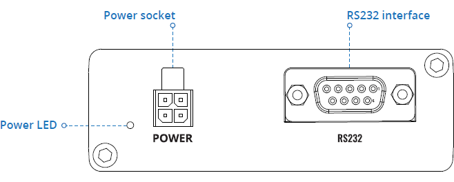
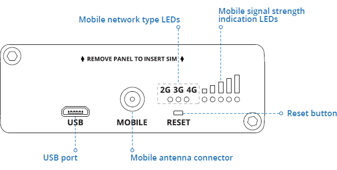
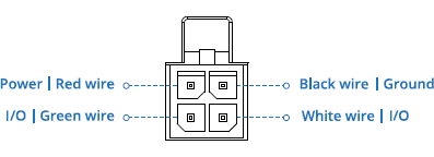
Main Page > TRB Gateways > TRB142 > TRB142 Manual > TRB142 Front & Back PanelsThis page provides descriptions of the components found on the front and back panels of a TRB142 device. For more information about connectors, visit Serial Utilities and Input/Output pages.


