DMVPN with IPsec Phase 3: Difference between revisions
mNo edit summary |
PauliusRug (talk | contribs) No edit summary |
||
| (45 intermediate revisions by 2 users not shown) | |||
| Line 1: | Line 1: | ||
<p style="color:red">The information in this page is updated in accordance with [https://wiki.teltonika-networks.com/view/FW_%26_SDK_Downloads'''00.07.03.2'''] firmware version. .</p> | |||
==Introduction== | ==Introduction== | ||
| Line 7: | Line 9: | ||
'''DMVPN''' has three phases that route data differently: | '''DMVPN''' has three phases that route data differently: | ||
Phase 1: All traffic | Phase 1: All traffic goes from the spoke to and through the hub. | ||
Phase 2: | Phase 2: Starts with Phase 1 and after it allows spoke-to-spoke tunnels. Phase 2 has different routing, where packet forwarding is being done using the IP routing table. Spokes reach other spokes networks based on the next-hop tunnel IP address of the other spoke for a particular network. | ||
Phase 3: | Phase 3: Improves the scalability and has fewer restrictions than Phase 2. Phase 3 allows the summarization of routes from hub to spokes. Spokes don’t even need routes, they can use the default gateway toward the hub router. | ||
| Line 21: | Line 23: | ||
<ul> | <ul> | ||
<li>2 Teltonika Routers for SPOKES</li> | <li>2 Teltonika Routers for '''SPOKES'''</li> | ||
<li>1 Teltonika Router for HUB with a public IP address</li> | <li>1 Teltonika Router for '''HUB''' with a public IP address</li> | ||
<li>A PC to configure the routers</li> | <li>A PC to configure the routers</li> | ||
</ul> | </ul> | ||
==Configuration scheme== | |||
[[File:DMVPN phase3 topology.png|border|class=tlt-border|1053x1053px]] | |||
=== | ==The SETUP== | ||
<b> | The following section contains information on how to configure DMVPN <b>HUB</b>. Firstly, we'll configure the DMVPN instance to make the connection possible. Then we'll set the <b>Border Gateway Protocol</b> (<b>BGP</b>) parameters as our dynamic routing solution. | ||
<b>Notes</b>: | |||
- | - At the moment, BGP is the only stable dynamic routing solution that can work with DMVPN. | ||
- If you are using non RUTX device, BGP and DMVPN have to be installed manually from the '''Services → Package Manager''' tab before continuing. | |||
- If you're having trouble finding any page or some of the parameters described here on your device's WebUI, you should turn on "Advanced WebUI" mode. You can do that by clicking the "Basic" button under "Mode," which is located at the top-right corner of the WebUI. | |||
[[File:1004px-Basic WebUI Advanced.gif|alt=|border]] | |||
- | ===HUB configuration: DMVPN=== | ||
---- | |||
Navigate to the <b>Services → VPN → DMVPN</b> page and follow the instructions provided below. | |||
< | <b>Step 1</b>: create a new DMVPN instance: | ||
1. Select your HUB interface in the Tunnel source field | |||
2. Set Local GRE interface IP address (for example, 10.0.0.254) | |||
3. Set GRE interface netmask to 255.255.255.255 | |||
4. Set GRE MTU value to 1420 (or even slightly lower - 1400 if a mobile interface is used) | |||
- | - Outbound/inbound keys are optional, for this example we will leave it at default | ||
- | 5. Set IPsec Pre-shared key (we used simple 123456 for this example) | ||
- | <br>[[File:HUB main.png|border|class=tlt-border]] | ||
---- | |||
<b>Step 2</b>: configure '''DMVPN Phase 1''' parameters: | |||
1. Encryption algorithm - AES 128 | |||
2. Authentication SHA256 | |||
3. DH group - MODP3072 | |||
<br>[[File:Hub phase1.png|border|class=tlt-border]] | |||
<br>[[File: | |||
---- | ---- | ||
<b>Step 3</b>: configure DMVPN Phase 2 parameters: | <b>Step 3</b>: configure '''DMVPN Phase 2''' parameters: | ||
1. Encryption algorithm - AES 128 | |||
2. Hash algorithm - SHA256 | |||
3. PFS group -MODP3072 | |||
<br>[[File: | <br>[[File:Hub phase2 fix.png|border|class=tlt-border]] | ||
---- | ---- | ||
<b>Step 4</b>: configure DMVPN NHRP parameters: | <b>Step 4</b>: configure '''DMVPN NHRP''' parameters: | ||
In the NHRP parameters section, it is important to enable '''REDIRECT''' option, which is essential to our Phase 3 configuration. | |||
<br>[[File: | <br>[[File:Redirect.png|border|class=tlt-border]] | ||
---- | ---- | ||
<b>Step 5</b>: save changes | <b>Step 5</b>: save changes | ||
===Hub configuration: BGP=== | ===Hub configuration: BGP === | ||
Navigate to the <b>Network → Routing → Dynamic Routes → BGP Protocol</b> page and follow the instructions provided below. | Navigate to the <b>Network → Routing → Dynamic Routes → BGP Protocol</b> page and follow the instructions provided below. | ||
<b>Step 1</b>: enable BGP and configure General section: | <b>Step 1</b>: enable '''BGP''' and configure General section: | ||
1. Enable vty | |||
2. Set AS to 65000 | |||
3. Set BGP router ID for easier management. | |||
4. Set announcement network(s). Routes to these networks will be shared over BGP. We used 192.168.1.0/24 | |||
5. "NHRP routes" selection should be applied under the "Redistribution options" section | |||
<br>[[File: | <br>[[File:Hub bgp.png|border|class=tlt-border]] | ||
---- | ---- | ||
<b>Step 2</b>: Create BGP Peer Group: | <b>Step 2</b>: Create '''BGP''' Peer Group: | ||
- Add Neighbor address (We used 10.0.0.1 and 10.0.0.2) | - Add a Neighbor address for SPOKE 1 and SPOKE 2 (We used 10.0.0.1 and 10.0.0.2 which will be in the same subnet as our hub 10.0.0.254) | ||
- Leave other settings as default. | |||
<br>[[File:Bgp peer grp.png|border|class=tlt-border]] | |||
<br>[[File: | |||
---- | ---- | ||
<b>Step 3</b>: Add two BGP peers for each spoke: | <b>Step 3</b>: Add two '''BGP''' peers for each spoke: | ||
Now let's create BGP peers for Spokes on the same page. Add two new BGP peers with the following parameters: | |||
Peer 1. | Peer 1. | ||
| Line 149: | Line 139: | ||
- Set Remote address as 10.0.0.2 | - Set Remote address as 10.0.0.2 | ||
We will keep other settings as their default values for this configuration example. | |||
<br>[[File: | <br>[[File:Bgp peer1.png|border|class=tlt-border]] | ||
---- | ---- | ||
[[File: | [[File:Bgp peer2.png|border|class=tlt-border]] | ||
---- | ---- | ||
===Spoke 1 configuration: DMVPN=== | === Spoke 1 configuration: DMVPN=== | ||
---- | ---- | ||
| Line 166: | Line 155: | ||
<b>Step 1</b>: create a new DMVPN instance: | <b>Step 1</b>: create a new DMVPN instance: | ||
1. Add HUB address (this is the public IP address of the previously configured hub device) | |||
2. Select Tunnel source (this is the egress interface, which will be able to reach the hub device's public IP address over the internet) | |||
3. Add Local GRE interface IP address (this is the GRE IP address of "Spoke 1". It should be unique in the entire VPN network) | |||
4. Add Remote GRE interface IP address (this is the GRE IP address of the previously configured hub device) | |||
5. Set GRE MTU to 1420 (this value should be set to the same value that was configured on the hub device. In our case, it is "1420") | |||
6. Set Local identifier (For setups behind NAT), Remote identifier as %any and input the same Pre-shared key (This will determine how other devices will be identified for authentication) | |||
<br>[[File:Spoke dmvpn.png|border|class=tlt-border]] | |||
<br>[[File: | |||
---- | ---- | ||
<b>Step 2</b>: configure DMVPN Phase 1 parameters: | <b>Step 2</b>: configure '''DMVPN''' '''Phase 1''' parameters: | ||
1. Select the Encryption algorithm - AES 128 | |||
2. Select Authentication SHA256 | |||
3. Select DH group MODP3072 | |||
<br>[[File:Hub phase1.png|border|class=tlt-border]] | |||
<br>[[File: | |||
---- | ---- | ||
<b>Step 3</b>: configure DMVPN Phase 2 parameters: | <b>Step 3</b>: configure '''DMVPN Phase 2''' parameters: | ||
1. Select the Encryption algorithm AES 128 | |||
2. Select Hash algorithm SHA256 | |||
3. Select PFS group MODP3072 | |||
<br>[[File:Hub phase2 fix.png|border|class=tlt-border]] | |||
---- | |||
< | <b>Step 4</b>: configure '''DMVPN NHRP''' parameters: | ||
- In the NHRP parameters section, it is important to enable REDIRECT option, which is essential to our Phase 3 configuration. | |||
- Leave everything by default | - Leave everything by default | ||
<br>[[File:Redirect.png|border|class=tlt-border]] | |||
---- | ---- | ||
<b>Step 5</b>: save changes | <b>Step 5</b>: save changes | ||
===Spoke 1 configuration: BGP=== | ===Spoke 1 configuration: BGP === | ||
Navigate to the <b>Network → Routing → Dynamic Routes → BGP Protocol</b> page and follow the instructions provided below. | Navigate to the <b>Network → Routing → Dynamic Routes → BGP Protocol</b> page and follow the instructions provided below. | ||
<b>Step 1</b>: enable BGP and configure General section: | <b>Step 1</b>: enable '''BGP''' and configure General section: | ||
1. Enable vty | |||
2. Set AS to 65001 | |||
3. Set Network to 192.168.10.0/24 | |||
<br>[[File: | <br>[[File:Spoke bgp.png|border|class=tlt-border]] | ||
---- | ---- | ||
<b>Step 2</b>: Create BGP Peer: | <b>Step 2</b>: Create '''BGP''' Peer: | ||
- Set Remote AS to 65000 | - Set Remote AS to 65000 | ||
- Set Remote address to 10.0.0.254 | - Set the Remote address to 10.0.0.254 | ||
- Leave everything else as default value | |||
<br>[[File: | <br>[[File:Spoke bgp peer.png|border|class=tlt-border]] | ||
===Spoke 2 configuration: DMVPN=== | ===Spoke 2 configuration: DMVPN=== | ||
< | Navigate to the <b>Services → VPN → DMVPN</b> page and follow the instructions provided below. | ||
<b>Step 1</b>: create a new DMVPN instance: | |||
1. Add HUB address (this is the public IP address of the previously configured hub device) | |||
2. Select Tunnel source (this is the egress interface, which will be able to reach the hub device's public IP address over the internet) | |||
3. Add Local GRE interface IP address (this is the GRE IP address of "Spoke 2". It should be unique in the entire VPN network) | |||
4. Add Remote GRE interface IP address (this is the GRE IP address of the previously configured hub device) | |||
5. Set GRE MTU to 1420 (this value should be set to the same value that was configured on the hub device. In our case, it is "1420") | |||
- | 6. Set Local identifier (For setups behind NAT), Remote identifier as %any and input the same Pre-shared key (This will determine how other devices will be identified for authentication) | ||
<br>[[File: | <br>[[File:Spoke2 dmvpn.png|border|class=tlt-border]] | ||
---- | ---- | ||
<b>Step 2</b>: configure DMVPN Phase 1 parameters: | <b>Step 2</b>: configure '''DMVPN Phase 1''' parameters: | ||
1. Select Encryption algorithm - AES 128 | |||
2. Select Authentication SHA256 | |||
3. Select DH group MODP3072 | |||
<br>[[File: | <br>[[File:Hub phase1.png|border|class=tlt-border]] | ||
---- | ---- | ||
<b>Step 3</b>: configure DMVPN Phase 2 parameters: | <b>Step 3</b>: configure '''DMVPN Phase 2''' parameters: | ||
1. Select Encryption algorithm AES 128 | |||
2. Select Hash algorithm SHA256 | |||
3. Select PFS group MODP3072 | |||
<br>[[File: | <br>[[File:Hub phase2 fix.png|border|class=tlt-border]] | ||
---- | ---- | ||
<b>Step 4</b>: configure DMVPN NHRP parameters: | <b>Step 4</b>: configure '''DMVPN NHRP''' parameters: | ||
<br>[[File: | - In the NHRP parameters section, it is important to enable REDIRECT option, which is essential to our Phase 3 configuration. | ||
- Leave everything by default | |||
<br>[[File:Redirect.png|border|class=tlt-border]] | |||
---- | ---- | ||
<b>Step 5</b>: save changes | <b>Step 5</b>: save changes | ||
===Spoke 2 configuration: BGP=== | ===Spoke 2 configuration: BGP === | ||
Navigate to the <b>Network → Routing → Dynamic Routes → BGP Protocol</b> page and follow the instructions provided below. | Navigate to the <b>Network → Routing → Dynamic Routes → BGP Protocol</b> page and follow the instructions provided below. | ||
<b>Step 1</b>: enable BGP and configure General section: | <b>Step 1</b>: enable '''BGP''' and configure General section: | ||
1. Enable vty | |||
2. Set AS to 65002 | |||
3. Set Network to 192.168.20.0/24 | |||
<br>[[File: | <br>[[File:Spoke2 bgp peer.png|border|class=tlt-border]] | ||
---- | ---- | ||
<b>Step 2</b>: Create BGP Peer: | <b>Step 2</b>: Create '''BGP''' Peer: | ||
- Set Remote AS to 65000 | - Set Remote AS to 65000 | ||
| Line 318: | Line 307: | ||
- Set Remote address to 10.0.0.254 | - Set Remote address to 10.0.0.254 | ||
- Leave everything else as default value | |||
<br>[[File:Spoke bgp peer.png|border|class=tlt-border]] | |||
---- | |||
===Important Note=== | ===Important Note=== | ||
For '''HUB''' in Network <b>→</b> Firewall GRE zone change from '''REJECT''' to '''ACCEPT''' on '''FORWARD.''' | |||
Also, disable '''Masquerading''' on '''HUB''' and '''ALL spokes''' for GRE <b>→</b> LAN zone forwardings | |||
[[File:Firewall new.png|alt=|border]] | |||
===Testing configuration=== | |||
'''- ipsec statusall''' command can be used in the CLI/SSH for testing the tunnel. It will return detailed status information either on connection or if the argument is lacking, on all connections. If everything was done correctly, it should display that tunnel has been established. | |||
'''- ping''' command can be used to check if the HUB and SPOKES can reach each other. | |||
[[File:Ping.png|alt=|border]] | |||
-- | [[File:Ping2.png|alt=|border]] | ||
[[File: | |||
- | - Check routes in the HUB by executing command '''vtysh -c "show ip nhrp"''' | ||
[[File:Vtysh nhrp2.jpg|alt=|border]] | |||
- If you need to reboot tunnel, execute '''/etc/init.d/ipsec retart''' | |||
== Summary == | |||
At this point, the basic DMVPN configuration is complete and phase 3 will now take effect in order to dynamically establish connectivity between spokes. Using this method, additional spokes may be configured and added to the current topology. DMVPN Phase 3 technology will ensure that any newly introduced devices will be included in the final topology. | |||
== References == | |||
[https://wiki.teltonika-networks.com/view/VPN_Configuration_Examples VPN configuration Examples] | |||
[https://wiki.teltonika-networks.com/view/DMVPN_configuration DMVPN configuration example] | |||
[https://wiki.teltonika-networks.com/view/IPsec_configuration_examples IPsec configuration example] | |||
[https://wiki.teltonika-networks.com/view/Routing#BGP_Protocol BGP routing] | |||
[ | |||
[https://docs.strongswan.org/docs/5.9/index.html strongSwan Documentation] | |||
[[Category:VPN]] | |||
Revision as of 13:52, 2 August 2023
Main Page > General Information > Configuration Examples > VPN > DMVPN with IPsec Phase 3The information in this page is updated in accordance with 00.07.03.2 firmware version. .
Introduction
DMVPN (Dynamic Multipoint Virtual Private Network) is a dynamic tunneling form of a virtual private network capable of creating a VPN network without having pre-configure all possible tunnel end-point peers. DMVPN is initially configured to build out a HUB and SPOKE network, where each new SPOKE can join the network with minimal effort. The main benefits of DMVPN would be that it simplifies router configuration, has high scalability, good performance with better bandwidth, and secure routing when used in combination with IPsec.
DMVPN has three phases that route data differently:
Phase 1: All traffic goes from the spoke to and through the hub.
Phase 2: Starts with Phase 1 and after it allows spoke-to-spoke tunnels. Phase 2 has different routing, where packet forwarding is being done using the IP routing table. Spokes reach other spokes networks based on the next-hop tunnel IP address of the other spoke for a particular network.
Phase 3: Improves the scalability and has fewer restrictions than Phase 2. Phase 3 allows the summarization of routes from hub to spokes. Spokes don’t even need routes, they can use the default gateway toward the hub router.
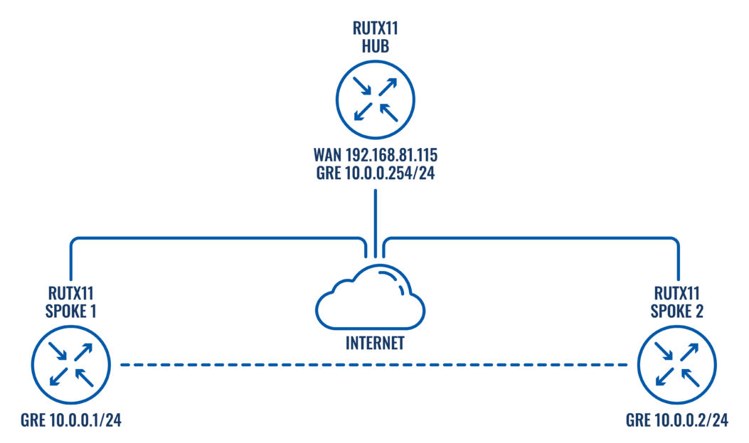
This article contains instructions on how to configure DMVPN Phase 3 between a "Hub" and two "Spokes" using Teltonika devices.
Prerequisites and overview
You will need:
- 2 Teltonika Routers for SPOKES
- 1 Teltonika Router for HUB with a public IP address
- A PC to configure the routers
Configuration scheme
The SETUP
The following section contains information on how to configure DMVPN HUB. Firstly, we'll configure the DMVPN instance to make the connection possible. Then we'll set the Border Gateway Protocol (BGP) parameters as our dynamic routing solution.
Notes:
- At the moment, BGP is the only stable dynamic routing solution that can work with DMVPN.
- If you are using non RUTX device, BGP and DMVPN have to be installed manually from the Services → Package Manager tab before continuing.
- If you're having trouble finding any page or some of the parameters described here on your device's WebUI, you should turn on "Advanced WebUI" mode. You can do that by clicking the "Basic" button under "Mode," which is located at the top-right corner of the WebUI.

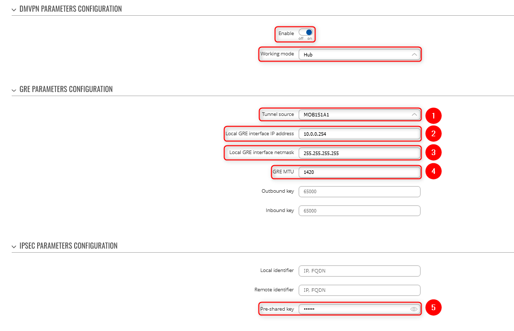
HUB configuration: DMVPN
Navigate to the Services → VPN → DMVPN page and follow the instructions provided below.
Step 1: create a new DMVPN instance:
1. Select your HUB interface in the Tunnel source field
2. Set Local GRE interface IP address (for example, 10.0.0.254)
3. Set GRE interface netmask to 255.255.255.255
4. Set GRE MTU value to 1420 (or even slightly lower - 1400 if a mobile interface is used)
- Outbound/inbound keys are optional, for this example we will leave it at default
5. Set IPsec Pre-shared key (we used simple 123456 for this example)
Step 2: configure DMVPN Phase 1 parameters:
1. Encryption algorithm - AES 128
2. Authentication SHA256
3. DH group - MODP3072
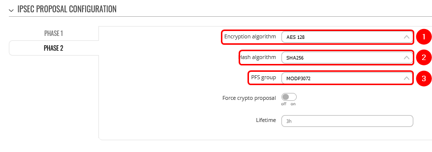
Step 3: configure DMVPN Phase 2 parameters:
1. Encryption algorithm - AES 128
2. Hash algorithm - SHA256
3. PFS group -MODP3072
Step 4: configure DMVPN NHRP parameters:
In the NHRP parameters section, it is important to enable REDIRECT option, which is essential to our Phase 3 configuration.
Step 5: save changes
Hub configuration: BGP
Navigate to the Network → Routing → Dynamic Routes → BGP Protocol page and follow the instructions provided below.
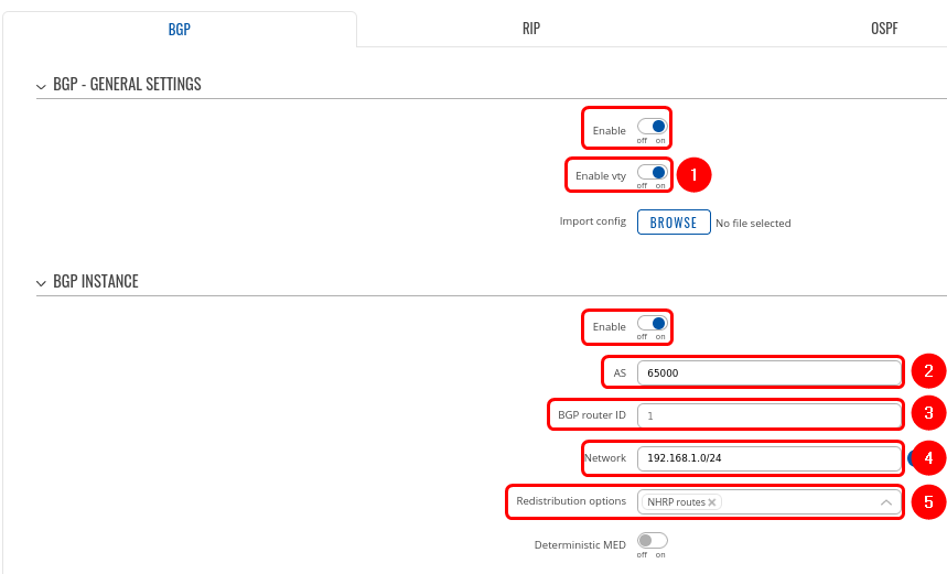
Step 1: enable BGP and configure General section:
1. Enable vty
2. Set AS to 65000
3. Set BGP router ID for easier management.
4. Set announcement network(s). Routes to these networks will be shared over BGP. We used 192.168.1.0/24
5. "NHRP routes" selection should be applied under the "Redistribution options" section
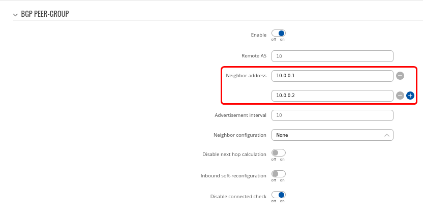
Step 2: Create BGP Peer Group:
- Add a Neighbor address for SPOKE 1 and SPOKE 2 (We used 10.0.0.1 and 10.0.0.2 which will be in the same subnet as our hub 10.0.0.254)
- Leave other settings as default.
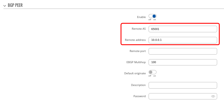
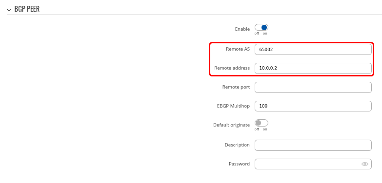
Step 3: Add two BGP peers for each spoke:
Now let's create BGP peers for Spokes on the same page. Add two new BGP peers with the following parameters:
Peer 1.
- Set Remote AS to 65001
- Set Remote address as 10.0.0.1
Peer 2.
- Set Remote AS to 65002
- Set Remote address as 10.0.0.2
We will keep other settings as their default values for this configuration example.
Spoke 1 configuration: DMVPN
Navigate to the Services → VPN → DMVPN page and follow the instructions provided below.
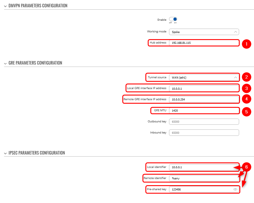
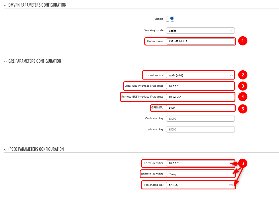
Step 1: create a new DMVPN instance:
1. Add HUB address (this is the public IP address of the previously configured hub device)
2. Select Tunnel source (this is the egress interface, which will be able to reach the hub device's public IP address over the internet)
3. Add Local GRE interface IP address (this is the GRE IP address of "Spoke 1". It should be unique in the entire VPN network)
4. Add Remote GRE interface IP address (this is the GRE IP address of the previously configured hub device)
5. Set GRE MTU to 1420 (this value should be set to the same value that was configured on the hub device. In our case, it is "1420")
6. Set Local identifier (For setups behind NAT), Remote identifier as %any and input the same Pre-shared key (This will determine how other devices will be identified for authentication)
Step 2: configure DMVPN Phase 1 parameters:
1. Select the Encryption algorithm - AES 128
2. Select Authentication SHA256
3. Select DH group MODP3072
Step 3: configure DMVPN Phase 2 parameters:
1. Select the Encryption algorithm AES 128
2. Select Hash algorithm SHA256
3. Select PFS group MODP3072
Step 4: configure DMVPN NHRP parameters:
- In the NHRP parameters section, it is important to enable REDIRECT option, which is essential to our Phase 3 configuration.
- Leave everything by default
Step 5: save changes
Spoke 1 configuration: BGP
Navigate to the Network → Routing → Dynamic Routes → BGP Protocol page and follow the instructions provided below.
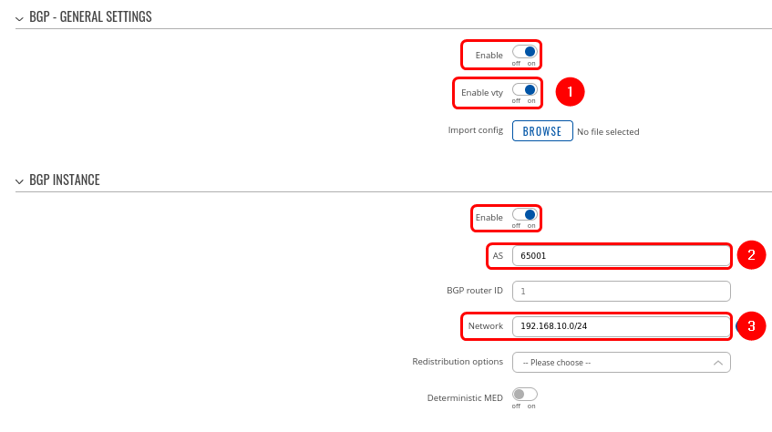
Step 1: enable BGP and configure General section:
1. Enable vty
2. Set AS to 65001
3. Set Network to 192.168.10.0/24
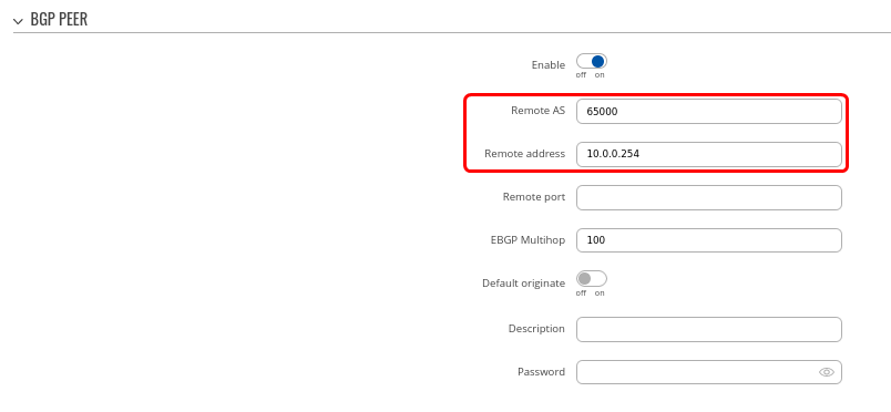
Step 2: Create BGP Peer:
- Set Remote AS to 65000
- Set the Remote address to 10.0.0.254
- Leave everything else as default value
Spoke 2 configuration: DMVPN
Navigate to the Services → VPN → DMVPN page and follow the instructions provided below.
Step 1: create a new DMVPN instance:
1. Add HUB address (this is the public IP address of the previously configured hub device)
2. Select Tunnel source (this is the egress interface, which will be able to reach the hub device's public IP address over the internet)
3. Add Local GRE interface IP address (this is the GRE IP address of "Spoke 2". It should be unique in the entire VPN network)
4. Add Remote GRE interface IP address (this is the GRE IP address of the previously configured hub device)
5. Set GRE MTU to 1420 (this value should be set to the same value that was configured on the hub device. In our case, it is "1420")
6. Set Local identifier (For setups behind NAT), Remote identifier as %any and input the same Pre-shared key (This will determine how other devices will be identified for authentication)
Step 2: configure DMVPN Phase 1 parameters:
1. Select Encryption algorithm - AES 128
2. Select Authentication SHA256
3. Select DH group MODP3072
Step 3: configure DMVPN Phase 2 parameters:
1. Select Encryption algorithm AES 128
2. Select Hash algorithm SHA256
3. Select PFS group MODP3072
Step 4: configure DMVPN NHRP parameters:
- In the NHRP parameters section, it is important to enable REDIRECT option, which is essential to our Phase 3 configuration.
- Leave everything by default
Step 5: save changes
Spoke 2 configuration: BGP
Navigate to the Network → Routing → Dynamic Routes → BGP Protocol page and follow the instructions provided below.
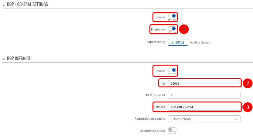
Step 1: enable BGP and configure General section:
1. Enable vty
2. Set AS to 65002
3. Set Network to 192.168.20.0/24
Step 2: Create BGP Peer:
- Set Remote AS to 65000
- Set Remote address to 10.0.0.254
- Leave everything else as default value
Important Note
For HUB in Network → Firewall GRE zone change from REJECT to ACCEPT on FORWARD.
Also, disable Masquerading on HUB and ALL spokes for GRE → LAN zone forwardings
Testing configuration
- ipsec statusall command can be used in the CLI/SSH for testing the tunnel. It will return detailed status information either on connection or if the argument is lacking, on all connections. If everything was done correctly, it should display that tunnel has been established.
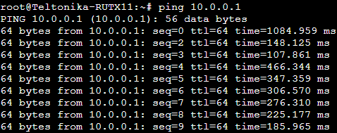
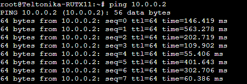
- ping command can be used to check if the HUB and SPOKES can reach each other.
- Check routes in the HUB by executing command vtysh -c "show ip nhrp"
- If you need to reboot tunnel, execute /etc/init.d/ipsec retart
Summary
At this point, the basic DMVPN configuration is complete and phase 3 will now take effect in order to dynamically establish connectivity between spokes. Using this method, additional spokes may be configured and added to the current topology. DMVPN Phase 3 technology will ensure that any newly introduced devices will be included in the final topology.

