|
|
| (13 intermediate revisions by the same user not shown) |
| Line 1: |
Line 1: |
| − | <p style="color:red">The information on this page is updated in accordance with the [https://wiki.teltonika-networks.com/view/FW_%26_SDK_Downloads'''00.07.4'''] firmware version .</p> | + | <p style="color:red">The information on this page is updated in accordance with the [https://wiki.teltonika-networks.com/view/FW_%26_SDK_Downloads'''00.07.08'''] firmware version .</p> |
| | __TOC__ | | __TOC__ |
| | ==Summary== | | ==Summary== |
| − | In this guide, Modbus TCP master MQTT Gateway function will be configured with two different types of MQTT Brokers. First using third-party MQTT Broker services (in this example ''Flespi.io''). Second, using another router as MQTT Broker. Two RUT955 routers will be used as Modbus TCP Master and Slave, and the PC acts as MQTT Publisher and Subscriber.
| + | This article contains instructions on how to send M-Bus data to the server using various protocols. |
| | | | |
| | ==Configuration overview & prerequisites== | | ==Configuration overview & prerequisites== |
| − | *Two RUT955 routers - one acts as Modbus TCP Master, another as Modbus TCP Slave
| + | Before we begin, let's take a look at the configuration that we are attempting to achieve and the prerequisites that make it possible. |
| − | *Flespi.io account to act as an MQTT Broker/Publisher/Subscriber (for first configuration example)
| |
| − | *RUT with a Public IP address to act as MQTT Broker (for second configuration example)
| |
| − | *An end device (PC, Laptop) to act as MQTT Subscriber/Publisher (for second configuration example)
| |
| | | | |
| − | ==Configuration using flespi.io as MQTT Broker==
| + | '''Prerequisites''': |
| − | [[File:Networking Topology MQTT MODBUS flespi configuration v1.png|center|class=tlt-border|800x800px]]
| + | * TRB143; |
| | + | * M-Bus device; |
| | + | * Server; |
| | + | * An end device (PC, Laptop, Tablet, Smartphone) for configuration; |
| | | | |
| − | ===Configuring RUT955 Modbus TCP Slave===
| |
| − | ----
| |
| − | Go to '''Services → Modbus → Modbus TCP Slave''':
| |
| | | | |
| − | #Check '''Enable'''
| + | {{Template:Networking_rutos_manual_basic_advanced_webui_disclaimer |
| − | #Enter port that will be used, in this example 502 will be used
| + | | series = RUTX |
| − | #Enter device ID
| + | }} |
| − | #Press '''Save & Apply'''
| + | |
| − | [[File:Networking_MQTT_MODBUS_flespi_configuration_slave1_v1.png|border|class=tlt-border|1044x1044px]]
| |
| | | | |
| − | ''*In this configuration LAN port is used hence “Allow Remote Access” is not needed''
| + | ==Adding M-Bus devices== |
| | + | To add a new device to the configuration press [[File:Add Button.png|60x90px]] button which is shown below. |
| | | | |
| − | ''Modbus TCP Slave RUT955 is now configured''.
| + | [[File:Mbus adding new device.png||border|class=tlt-border]] |
| | | | |
| − | ===Configuring RUT955 Modbus TCP Master=== | + | ===Device configuration=== |
| | ---- | | ---- |
| − | Go to '''Services → Modbus → Modbus TCP Master'''
| + | You will be granted to a new window. Configure your M-Bus device accordingly: |
| − | | |
| − | #Press '''Add'''
| |
| − | # Check '''Enable'''
| |
| − | # Enter the name for the slave device
| |
| − | # Slave ID must match with the previously configured Slave device ID
| |
| − | #Enter the IP address of the Modbus TCP Slave device
| |
| − | #Chose same Port as in Slave device - 502
| |
| − | #Enter Period in seconds, how often requests will be sent to the Slave device
| |
| − | #Enter new request name and press '''Add''' in Requests configurations
| |
| − | #Choose Data type and Function, enter First register/coil/input to be read or written and Register count. You can name each individual configuration, and then select enable on configurations that you want to use. In this example, register to get Routers name is used.
| |
| − | #Press the Test button in Request Configuration Testing to see if the Slave device responds to requests, a response similar to the image below should be shown.
| |
| − | #Press Save & Apply
| |
| − | ''List of available Modbus parameters can be found [https://wiki.teltonika-networks.com/view/RUT955_Monitoring_via_Modbus#Get_Parameters here]''
| |
| | | | |
| − | [[File:Networking_MQTT_MODBUS_flespi_configuration_master_add_v1.png|alt=|border|class=tlt-border|1007x1007px]]
| + | # '''Name''': Enter the desired name of the M-Bus device |
| | + | # '''Address type''': select which M-Bus address will be used |
| | + | # '''Primary/Secondary address''': specify M-Bus address |
| | | | |
| − | [[File:Networking MQTT MODBUS flespi configuration master afteradd step 234567 v2.png|border|class=tlt-border|1006x1006px]] | + | [[File:Mbus adding new device configuration v3.png|border|class=tlt-border]] |
| | | | |
| − | [[File:Networking MQTT MODBUS flespi configuration master req testing v3.png|border|class=tlt-border|1007x1007px]] | + | Test if the M-Bus device is reachable by a specified primary/secondary address. To do so click on [[File:Ping_device_option_mbus.png|110x110px]]. You might get on of two outputs: |
| | | | |
| − | ===Configuring Flespi.io MQTT Broker===
| + | * If you have specified correct primary/secondary address, you will receive: |
| − | ---- | + | [[File:Mbus device pingable v2.png|border|class=tlt-border|300px]] |
| − | #Log in or create an account on https://flespi.io
| |
| | | | |
| − | [[File:Networking MQTT Modbus flespiio login.png|border|class=tlt-border|842x842px]] | + | * If you have specified incorrect primary/secondary address, you will receive (if you do not know what address should be used, refer to the Scanning for available M-Bus devices (PRIDET URL) secion: |
| | + | [[File:Mbus device not pingable v2.png|border|class=tlt-border|300px]] |
| | | | |
| − | Once logged in: | + | Once finished, save the configuration by clicking [[File:Savenapply button.png|Savenapply button.png]]. |
| | | | |
| − | #Navigate to MQTT Board on the left side of the screen and press it.
| + | ===Scanning for available M-Bus devices=== |
| − | #On the right-hand panel, top right corner, next to the name of the MQTT board, press the cogwheel-looking icon to open ''Connection Settings''
| |
| − | #In the opened window, press "Get flespi token" to generate a username
| |
| − | #Enter Client name
| |
| − | #Copy Host address
| |
| − | #Copy Username
| |
| − | #Create a password
| |
| − | #Press Save
| |
| − | [[File:Networking MQTT modbus fespi Connection settings v1.png|border|class=tlt-border|544x544px]] [[File:Networking MQTT Modbus flespi board.png|border|class=tlt-border|544x544px]]
| |
| − | | |
| − | === Configuring MQTT Gateway on RUT955 Modbus TCP Master===
| |
| | ---- | | ---- |
| − | Open routers WebUI and navigate to '''Services → Modbus → MQTT Gateway'''
| |
| − |
| |
| − | #Select Enable
| |
| − | #Enter Host (copied from flespi connection settings without 'wss://' and port)
| |
| − | #Enter Username (Copied from flespi Connection settings generated token)
| |
| − | #Enter Password
| |
| − |
| |
| − | [[File:Networking MQTT Modbus Rut configuration Mqtt gateway v1.png|border|class=tlt-border|1058x1058px]]
| |
| | | | |
| − | ''You can change Request and Response topics that you will have to publish and subscribe to get information from Modbus TCP Master through MQTT Gateway, but for this example, they are left on default topics''
| + | If you are not sure what address your M-Bus devices have, you can try scanning for the available M-Bus devices. To do so click on [[File:Scan button.png]] button. |
| | | | |
| − | ===Message format for MQTT publisher=== | + | ====Scan settings==== |
| | ---- | | ---- |
| − | The format is in the text - heavier and slower, but less difficult to edit.
| + | You will be granted to a new window. Configure scan settings accordingly: |
| − | {| class="wikitable"
| |
| − | |1. Format version
| |
| − | |'''0'''
| |
| − | |-
| |
| − | |2. Cookie
| |
| − | |from '''0''' to '''2<sup>64</sup> -1'''
| |
| − | |-
| |
| − | |3. IP Type
| |
| − | |'''0''' - IPv4; '''1''' - IPv6; '''2''' - hostname
| |
| − | |-
| |
| − | |4. IP
| |
| − | |IPv6 must be in full format (for example: '''2001:0db8:0000:0000:0000:8a2e:0370:7334''')
| |
| − | |-
| |
| − | |5. Port
| |
| − | |Port number (for example: '''502''')
| |
| − | |-
| |
| − | |6. Timeout in seconds (time to wait for response)
| |
| − | |from '''1''' to '''999'''
| |
| − | |-
| |
| − | |7. Slave ID - Indicates to which slave request is sent
| |
| − | |from '''1''' to '''255'''
| |
| − | |-
| |
| − | |8. Function
| |
| − | |'''3''' - read registers; '''6''' - write single register; '''16''' - write multiple registers
| |
| − | |-
| |
| − | |9. Number of the first register from which information will be read or written
| |
| − | |from '''1''' to '''65535'''
| |
| − | |-
| |
| − | |10. Registry value
| |
| − | |If function is 3 - from '''1''' to '''123''' (first register + registry value can not go out of range);
| |
| − | If function is 6 - from '''0''' to '''65535'''
| |
| | | | |
| − | If function is 16 - from '''1''' to '''123''' (first register + registry value can not go out of range), Registry values separated by commas without spaces. Example.: '''1,2,3,654,21,789'''. There has to be as many values, as specified number of registers, and each value must be between '''0''' and '''65535'''. If number of registries is 0, there should be '''no registry values'''
| + | # '''Scan type''': select which M-Bus address will be scanned |
| − | |}
| + | # '''Scan range''': From what M-Bus address scanning will start and M-Bus address until scanning will be performed. |
| − | [[File:Networking MQTT modbus message format publisher v1.png|border|class=tlt-border]] | + | [[File:Mbus scan.png|border|class=tlt-border]] |
| | | | |
| − | ====Examples====
| + | To start the scan click on [[File:Start scan button.png]] button. |
| − | ----
| |
| − | {| class="wikitable"
| |
| − | |Setting relay (on) (Relay address is 202, which means 'Number of first register will be 203)
| |
| − | |'''0 65432 0 192.168.1.1 502 5 1 6 203 1'''
| |
| − | |-
| |
| − | |Getting uptime
| |
| − | |'''0 65432 0 192.168.1.1 502 5 1 3 2 2'''
| |
| − | |}
| |
| | | | |
| − | ===Testing MQTT Publisher and Subscriber on flespi.io=== | + | ====Found devices==== |
| | ---- | | ---- |
| − | Log in and navigate to MQTT Board on https://flespi.io
| + | Once the scan is finished you should see the list of M-Bus devices that TRB143 were able to find: |
| − | | |
| − | Add a Subscriber:
| |
| − | | |
| − | #Press '''''<nowiki/>'+'''''' button on the top right corner
| |
| − | #Select '''''<nowiki/>'Subscriber''''''
| |
| − | # In the topic field enter '''''<nowiki/>'response''''''
| |
| − | #Press '''''<nowiki/>'Subscribe'''''' button
| |
| − | | |
| − | [[File:Networking MQTT Modbus flespi subscriber config1 v1.png|border|class=tlt-border]] [[File:Networking MQTT Modbus flespi subscriber config2 v1.png|border|class=tlt-border]]
| |
| − | | |
| − | Add a Publisher:
| |
| − | | |
| − | #Press '''''<nowiki/>'+'''''' button on the top right corner
| |
| − | #Select '''''<nowiki/>'Publisher''''''
| |
| − | # In the topic field enter '''''<nowiki/>'request''''''
| |
| − | #In the message field enter message, for this example '''''<nowiki/>'Getting uptime'''''' is used
| |
| − | #Press '''''<nowiki/>'Publish'''''' button
| |
| − | | |
| − | [[File:Networking MQTT Modbus flespi publisher config1 v1.png|border|class=tlt-border|434x434px]] [[File:Networking MQTT Modbus flespi publisher config2 v1.png|border|class=tlt-border|365x365px]]
| |
| − | | |
| − | | |
| − | Check the response in the '''''<nowiki/>'Subscriber'''''' tab, you should receive a message similar to the one below.
| |
| − | | |
| | | | |
| − | [[File:Networking MQTT Modbus flespi Response v2.png|border|class=tlt-border|931x931px]] | + | [[File:Mbus scanned devices add.png|border|class=tlt-border]] |
| | | | |
| − | When the value climbs over 65535 the counter resets and the value held by the first register increases by '''1'''. So one way to interpret the results would be to multiply the value in the first register by '''2<sup>16</sup>''' and add it to the value of the second register. In this example: '''9 * 65536 + 3502 = 593326s''' or '''6 days 20 hours 48 minutes and 46 seconds.'''
| + | You can either [[File:Pencil2.png]] '''(1)''' M-Bus devices primary address or [[File:Add Button.png|60x90px]] '''(2)''' to the M-Bus devices list. |
| | | | |
| − | ''This Means that MQTT Gateway on Modbus TCP Master router is working correctly and Modbus TCP Slave receives requests.''
| + | ==Gathering M-Bus data== |
| | | | |
| − | ==Configuration using a router as MQTT Broker== | + | If the device successfully added to the list, under the General settings you should see that the Status changes to <span style="color:green">Active</span>. |
| | | | |
| − | [[File:Networking Topology MQTT MODBUS RUTbroker configuration v1.png|987x987px]] | + | [[File:Mbus status active v2.png|border|class=tlt-border]] |
| | | | |
| − | ===Configuring Modbus TCP Master, MQTT Gateway MQTT Broker on RUT240, and MQTT Publisher/Subscriber on PC=== | + | ===Data collecting groups=== |
| | ---- | | ---- |
| − | ''The same configuration will be used for Modbus TCP Master and Slave RUT955 routers as in the previous example, only settings in Modbus TCP Master router RUT955 will be changed to match MQTT Broker on RUT240 router''
| + | To reach data collecting groups configuration press [[File:Pencil2.png]] button. [[File:Add Button.png|60x90px]] button lets you to create a new instance. |
| | | | |
| − | Navigate to '''Services → Modbus MQTT Gateway'''
| + | [[File:Mbus data collect overview.png|border|class=tlt-border]] |
| | | | |
| − | #'''Enable'''
| + | ====Data collecting group instance==== |
| − | # Host: '''Enter Public IP address of MQTT Broker (RUT240)'''
| |
| − | #Username: '''N/A'''
| |
| − | #Password: '''N/A'''
| |
| − | #Press '''Save & Apply'''
| |
| − | | |
| − | [[File:Networking MQTT Modbus MQTT gateway config v1.png|border|class=tlt-border|1090x1090px]]
| |
| − | | |
| − | ===Configuring RUT MQTT Broker=== | |
| | ---- | | ---- |
| | | | |
| − | Navigate to '''Services → MQTT → Broker'''
| + | Each data collection group contains the following information. Configure device accordingly: |
| | | | |
| − | #Select '''Enable''' | + | # '''Enabled''': on |
| − | #Check '''Enable Remote Access''' | + | # '''Name''': desired name of the instance |
| − | #Press '''Save & Apply''' | + | # '''Period''': desired time duration between data retrievals |
| | + | # '''Data type''': desired data type to process the received data. You can choose from JSON, XML, ASCII, Hexadecimal and Binary formats. |
| | | | |
| − | [[File:Networking MQTT Modbus MQTT Broker RUTos config v1.png|border|class=tlt-border|1079x1079px]] | + | You can check if your configuration works accordingly by pressing the [[File:Mbus test button.png]] button. You should see the data in a pop-up field. |
| | | | |
| − | ===Testing MQTT Gateway=== | + | [[File:Mbus data collect group v2.png|border|class=tlt-border]] |
| − | ----
| |
| | | | |
| − | For testing purposes, two terminal windows will be used on the same PC.
| |
| | | | |
| − | ''To get Ubuntu terminal on Windows 10/11, refer to the following link for instructions:'' https://tutorials.ubuntu.com/tutorial/tutorial-ubuntu-on-windows#0
| + | ==See Also== |
| − | | |
| − | *Open first terminal, which will act as '''Subscriber'''. Type in:
| |
| − | | |
| − | <blockquote>''mosquitto_sub -h [Host_address] -p [Port] -t [Topic]''</blockquote>[[File:Networking MQTT Modbus Subscriber in terminal v1.png|border|class=tlt-border]]
| |
| − | | |
| − | *Open second terminal, which will act as '''Publisher.''' Type in:
| |
| | | | |
| − | <blockquote>''mosquitto_pub -h [Host_address] -p [Port] -m [‘Message’] -t [Topic]''</blockquote>[[File:Networking MQTT Modbus Publisher testing v1.png|border|class=tlt-border]]
| + | ==External links== |
| − | | + | [https://flespi.io/#/ Flespi.io] |
| − | *On the first window - '''Subscriber''', a response should appear
| |
| − | | |
| − | [[File:Networking MQTT Modbus Subscriber response ubuntu v1.png|border|class=tlt-border]]
| |
| − | | |
| − | ==See Also== | |
| − | *[[Modbus Master RutOS configuration example]]
| |
| − | *[[RUT955 Monitoring via Modbus#Get Parameters]]
| |
The information on this page is updated in accordance with the 00.07.08 firmware version .
Summary
This article contains instructions on how to send M-Bus data to the server using various protocols.
Configuration overview & prerequisites
Before we begin, let's take a look at the configuration that we are attempting to achieve and the prerequisites that make it possible.
Prerequisites:
- TRB143;
- M-Bus device;
- Server;
- An end device (PC, Laptop, Tablet, Smartphone) for configuration;
If you're having trouble finding this page or some of the parameters described here on your device's WebUI, you should turn on "Advanced WebUI" mode. You can do that by clicking the "Advanced" button, located at the top of the WebUI.

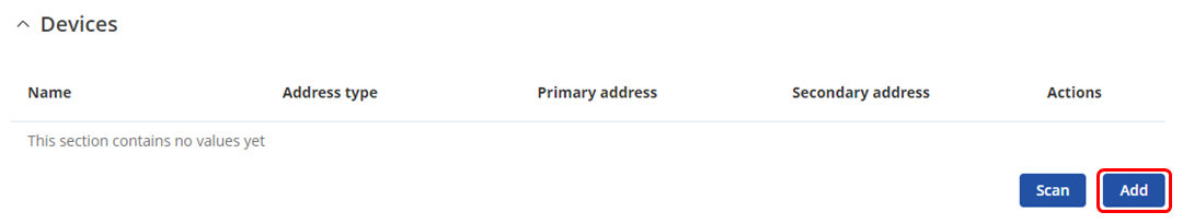
Adding M-Bus devices
To add a new device to the configuration press  button which is shown below.
Device configuration
You will be granted to a new window. Configure your M-Bus device accordingly:
- Name: Enter the desired name of the M-Bus device
- Address type: select which M-Bus address will be used
- Primary/Secondary address: specify M-Bus address
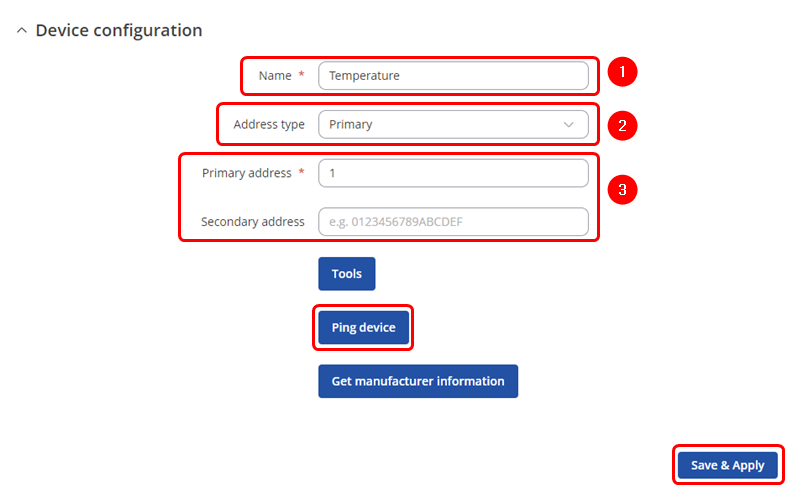
Test if the M-Bus device is reachable by a specified primary/secondary address. To do so click on  . You might get on of two outputs:
- If you have specified correct primary/secondary address, you will receive:
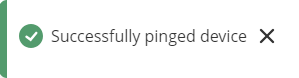
- If you have specified incorrect primary/secondary address, you will receive (if you do not know what address should be used, refer to the Scanning for available M-Bus devices (PRIDET URL) secion:

Once finished, save the configuration by clicking  .
.
Scanning for available M-Bus devices
If you are not sure what address your M-Bus devices have, you can try scanning for the available M-Bus devices. To do so click on  button.
Scan settings
You will be granted to a new window. Configure scan settings accordingly:
- Scan type: select which M-Bus address will be scanned
- Scan range: From what M-Bus address scanning will start and M-Bus address until scanning will be performed.
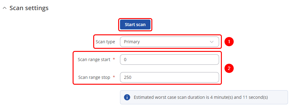
To start the scan click on  button.
Found devices
Once the scan is finished you should see the list of M-Bus devices that TRB143 were able to find:
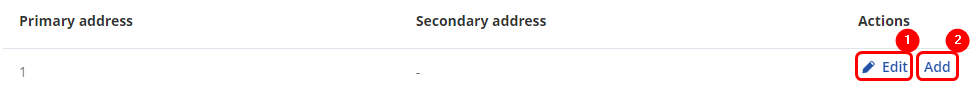
You can either  (1) M-Bus devices primary address or (2) to the M-Bus devices list.
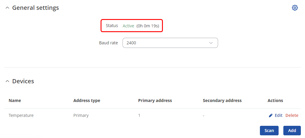
Gathering M-Bus data
If the device successfully added to the list, under the General settings you should see that the Status changes to Active.
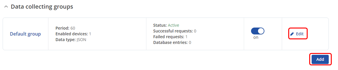
Data collecting groups
To reach data collecting groups configuration press button. button lets you to create a new instance.
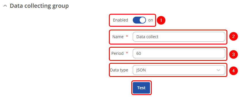
Data collecting group instance
Each data collection group contains the following information. Configure device accordingly:
- Enabled: on
- Name: desired name of the instance
- Period: desired time duration between data retrievals
- Data type: desired data type to process the received data. You can choose from JSON, XML, ASCII, Hexadecimal and Binary formats.
You can check if your configuration works accordingly by pressing the  button. You should see the data in a pop-up field.
See Also
External links
Flespi.io


