RUTX12 Traffic control with Firewall WANzone Splitting: Difference between revisions
(.) |
No edit summary |
||
| (42 intermediate revisions by 2 users not shown) | |||
| Line 1: | Line 1: | ||
<p style="color:red">The information in this page is updated in accordance with [https://wiki.teltonika-networks.com/view/FW_%26_SDK_Downloads'''00.07.08'''] firmware version.</p> | |||
==Introduction== | ==Introduction== | ||
This article contains instructions on how to configure mobile SIM traffic effectively, The configuration ensures that when SIM1 is active, it provides internet connectivity to all end devices. However, when SIM2 is being used, the configuration should impose restrictions on the traffic flow from PC2 and only traffic from. | This article contains instructions on how to configure mobile SIM traffic effectively, The configuration ensures that when SIM1 is active, it provides internet connectivity to all end devices. However, when SIM2 is being used, the configuration should impose restrictions on the traffic flow from PC2 and only traffic from. | ||
[[File: | [[File:Topology..png|border|center|class=tlt-border]] | ||
==Prerequisites== | ==Prerequisites== | ||
For this configuration you will need: | For this configuration you will need: | ||
* Teltonika Networks router with dual sim card support ( | * Teltonika Networks router with dual sim card support (RUTX12 is being used in the example); | ||
* 2 SIM cards; | * 2 SIM cards; | ||
* 2 end devices connected to the router (PC's are being used in the example); | * 2 end devices connected to the router (PC's are being used in the example); | ||
| Line 12: | Line 12: | ||
==Preparation== | ==Preparation== | ||
* Prepare | * Prepare RUTX12, power up the device, insert two sim cards, check that both are active and working. SIM1, SIM2, PWR, and signal strength indicators should light up. | ||
* Access the router through WEBUI, go to <b>Network -> Interfaces</b>, and make sure that one or the other mobile interference is running MOB1S1A1 or MOB2S1A1 (Status = Running). You should be able to see the IP address assigned to it. In addition, it is recommended to perform connectivity checking by using the ping utility. | * Access the router through WEBUI, go to <b>Network -> Interfaces</b>, and make sure that one or the other mobile interference is running MOB1S1A1 or MOB2S1A1 (Status = Running). You should be able to see the IP address assigned to it. In addition, it is recommended to perform connectivity checking by using the ping utility. | ||
* Make sure that you have ADVANCED mode enabled. This will allow you to choose from a larger variety of settings. | * Make sure that you have ADVANCED mode enabled. This will allow you to choose from a larger variety of settings. | ||
| Line 21: | Line 21: | ||
}} | }} | ||
=== Firewall General Settings === | === Firewall General Settings === | ||
The '''General Settings''' section is utilized for configuring the core policies of the device's firewall. | The '''General Settings''' section is utilized for configuring the core policies of the device's firewall. To access this configuration, proceed to: '''Network –> Firewall -> General Setting''' While maintaining the default settings for other options, click on the Edit symbol corresponding to the zones.<br> | ||
The '''Zones''' section is employed to oversee the default traffic forwarding policies among distinct zones within the device. Both "'''mob1s1a1'''" and "'''mob2s1a1'''" by default are situated within the same Firewall zone, signifying that identical rules are applied to both mobile interfaces/SIM cards. Consequently, any traffic restriction in this zone will simultaneously influence both SIM cards. As a result, it becomes necessary to create two distinct zones for each SIM individually. | |||
==== Editing existing firewall zone ==== | |||
# Go to '''Network→ Firewall→ General→ Zones''' | |||
# Locate the WAN zone and click on the '''edit button''' (pencil sign) | |||
[[File:RutOS_traffic_control_firewall_wanzone_split_7.8_1.png|border|center|class=tlt-border|1100px]] | |||
# Remove the '''mob2s1a1''' interface from the Default Firewall zone configuration | |||
# Save the settings by clicking '''Save & Apply''' button at the bottom right hand side | |||
[[File:RutOS_traffic_control_firewall_wanzone_split_7.8_2.png|border|center|class=tlt-border]] | |||
==== Create a new Zone: ==== | |||
----To create a new zone, simply click on the "Add" button located in the bottom right corner. | |||
[[File: | [[File:RutOS_traffic_control_firewall_wanzone_split_7.8_3.png|border|center|class=tlt-border|1100px]] | ||
By clicking on '''Add''' button as shown: | |||
# Choose a '''Name''' for this rule as per your preference. | |||
# Set the input to be in the "'''Reject'''" zone. | |||
# Designate the output to be in the "'''Accept'''" zone. | |||
# Configure the forward action to be directed to the "'''Reject'''" zone. | |||
# Activate both '''Masquerading''' and '''MSS clamping''' options. | |||
# In the "'''Covered'''" zone, select the SIM Interface individually. In the provided example, it will be "SIM2" identified as "mob2s1a1". | |||
# In the inter-zone section keep Allow forward from source zones as "'''lan'''" | |||
# Click on '''"Save & Apply"''' in the bottom right corner. | |||
[[File:RutOS_traffic_control_firewall_wanzone_split_7.8_4.png|border|center|class=tlt-border]] | |||
<br />Once you have created the new zone, it should resemble the following: | |||
[[File:RutOS_traffic_control_firewall_wanzone_split_7.8_5.png|border|center|class=tlt-border|1100px]] | |||
=== | === Traffic rule creation === | ||
---- | |||
To establish the traffic rule according to the zones you've set up, follow these steps '''Navigate to Network –> Firewall -> Traffic Rules''' to begin creating the rule. Create and set up the rule to enable the host's access to the web server. | |||
* In the '''<nowiki/>'''Add type field, select '''<nowiki/>'Add new forward rule''''. | |||
* Assign a Name of your choosing to this rule. | |||
* Choose "'''LAN'''" as the source zone. | |||
* Select "'''WAN2'''" as the destination zone. | |||
* Click the ''''Add'''<nowiki/>' button to confirm and add the rule. | |||
[[File:RutOS_traffic_control_firewall_wanzone_split_7.8_6.png|border|center|class=tlt-border|1100px]] | |||
=== Specify the source zone === | |||
Upon clicking '''<nowiki/>'Add'''' in the previous step, a new window will appear, enabling you to define additional configurations. | |||
[[File: | # '''Enable the instance'''; | ||
# Choose Protocol: '''All'''; | |||
# Choose the Source IP address '''the one to block, e.g. 192.168.11.228 in this case'''; | |||
# Choose Action: '''Reject'''; | |||
* Click on '''<nowiki/>'Save and Apply''''. | |||
[[File:RutOS_traffic_control_firewall_wanzone_split_7.8_7.png|border|center|class=tlt-border]] | |||
== | == Testing the configuration == | ||
If you have followed all the provided steps to test the firewall traffic rules and verify the configuration, here is the revised description: | |||
# Initially, ensure that your router's WAN is connected to SIM1. | |||
# From PC1, access the web UI and navigate to "Service" -> "CLI." | |||
# Log in using the username "root" and the router's admin password. | |||
# In the CLI, ping the IP address 8.8.8.8. If you receive a response, it confirms that internet connectivity is established through SIM1 mobile connectivity on PC1. | |||
# Perform the same procedure on PC2 by logging into the CLI and pinging the IP address 8.8.8.8. If you receive a response, it also confirms that internet connectivity is established via SIM1 on PC2. | |||
Next, switch the router's WAN connection to SIM2 and conduct the following tests: | |||
# Ping 8.8.8.8 from PC1. After logging into the CLI and pinging the IP address 8.8.8.8 If you receive a response, it indicates that SIM2 has internet connectivity. | |||
# Ping 8.8.8.8 from PC2. when pinging the IP address 8.8.8.8 from PC2 and If you experience 100% packet loss, it means that PC2 does not have internet connectivity via SIM2. | |||
These tests serve to validate the functionality of the firewall rules and the connectivity of the router's WAN connections. | |||
[[File:Testing Traffic rules.png|border|center|class=tlt-border]] | |||
You can specify additional settings as you wish. For example, you can set times when this rule should apply. This way, the host will be able to access the web server only at certain times. | |||
Latest revision as of 09:55, 9 August 2024
The information in this page is updated in accordance with 00.07.08 firmware version.
Introduction
This article contains instructions on how to configure mobile SIM traffic effectively, The configuration ensures that when SIM1 is active, it provides internet connectivity to all end devices. However, when SIM2 is being used, the configuration should impose restrictions on the traffic flow from PC2 and only traffic from.
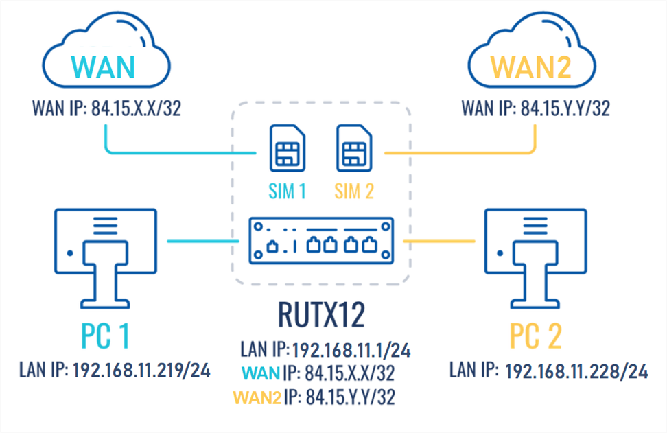
Prerequisites
For this configuration you will need:
- Teltonika Networks router with dual sim card support (RUTX12 is being used in the example);
- 2 SIM cards;
- 2 end devices connected to the router (PC's are being used in the example);
Preparation
- Prepare RUTX12, power up the device, insert two sim cards, check that both are active and working. SIM1, SIM2, PWR, and signal strength indicators should light up.
- Access the router through WEBUI, go to Network -> Interfaces, and make sure that one or the other mobile interference is running MOB1S1A1 or MOB2S1A1 (Status = Running). You should be able to see the IP address assigned to it. In addition, it is recommended to perform connectivity checking by using the ping utility.
- Make sure that you have ADVANCED mode enabled. This will allow you to choose from a larger variety of settings.
Configuration
If you're having trouble finding this page or some of the parameters described here on your device's WebUI, you should turn on "Advanced WebUI" mode. You can do that by clicking the "Advanced" button, located at the top of the WebUI.
Firewall General Settings
The General Settings section is utilized for configuring the core policies of the device's firewall. To access this configuration, proceed to: Network –> Firewall -> General Setting While maintaining the default settings for other options, click on the Edit symbol corresponding to the zones.
The Zones section is employed to oversee the default traffic forwarding policies among distinct zones within the device. Both "mob1s1a1" and "mob2s1a1" by default are situated within the same Firewall zone, signifying that identical rules are applied to both mobile interfaces/SIM cards. Consequently, any traffic restriction in this zone will simultaneously influence both SIM cards. As a result, it becomes necessary to create two distinct zones for each SIM individually.
Editing existing firewall zone
- Go to Network→ Firewall→ General→ Zones
- Locate the WAN zone and click on the edit button (pencil sign)

- Remove the mob2s1a1 interface from the Default Firewall zone configuration
- Save the settings by clicking Save & Apply button at the bottom right hand side
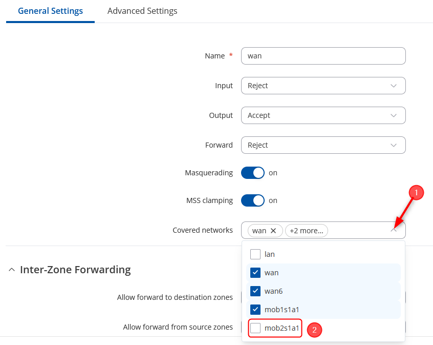
Create a new Zone:
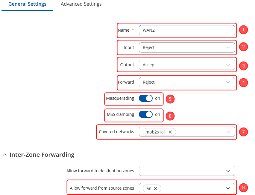
To create a new zone, simply click on the "Add" button located in the bottom right corner.

By clicking on Add button as shown:
- Choose a Name for this rule as per your preference.
- Set the input to be in the "Reject" zone.
- Designate the output to be in the "Accept" zone.
- Configure the forward action to be directed to the "Reject" zone.
- Activate both Masquerading and MSS clamping options.
- In the "Covered" zone, select the SIM Interface individually. In the provided example, it will be "SIM2" identified as "mob2s1a1".
- In the inter-zone section keep Allow forward from source zones as "lan"
- Click on "Save & Apply" in the bottom right corner.
Once you have created the new zone, it should resemble the following:

Traffic rule creation
To establish the traffic rule according to the zones you've set up, follow these steps Navigate to Network –> Firewall -> Traffic Rules to begin creating the rule. Create and set up the rule to enable the host's access to the web server.
- In the Add type field, select 'Add new forward rule'.
- Assign a Name of your choosing to this rule.
- Choose "LAN" as the source zone.
- Select "WAN2" as the destination zone.
- Click the 'Add' button to confirm and add the rule.

Specify the source zone
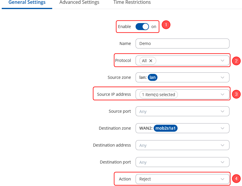
Upon clicking 'Add' in the previous step, a new window will appear, enabling you to define additional configurations.
- Enable the instance;
- Choose Protocol: All;
- Choose the Source IP address the one to block, e.g. 192.168.11.228 in this case;
- Choose Action: Reject;
- Click on 'Save and Apply'.
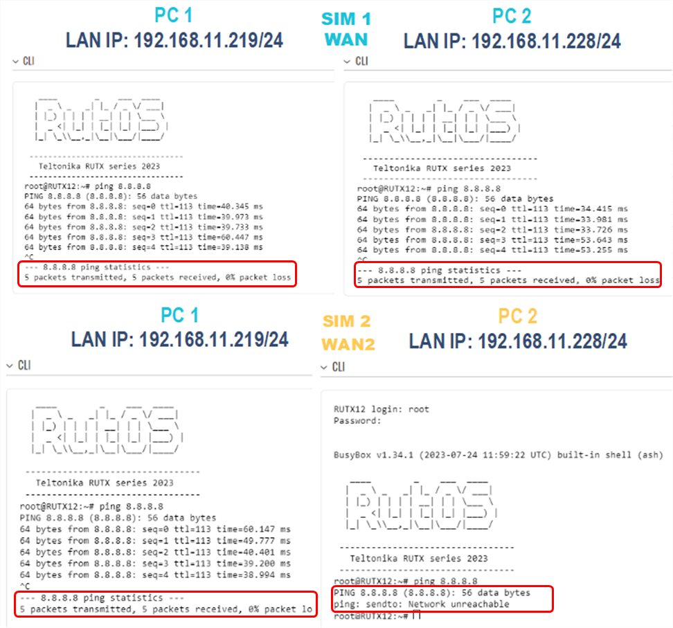
Testing the configuration
If you have followed all the provided steps to test the firewall traffic rules and verify the configuration, here is the revised description:
- Initially, ensure that your router's WAN is connected to SIM1.
- From PC1, access the web UI and navigate to "Service" -> "CLI."
- Log in using the username "root" and the router's admin password.
- In the CLI, ping the IP address 8.8.8.8. If you receive a response, it confirms that internet connectivity is established through SIM1 mobile connectivity on PC1.
- Perform the same procedure on PC2 by logging into the CLI and pinging the IP address 8.8.8.8. If you receive a response, it also confirms that internet connectivity is established via SIM1 on PC2.
Next, switch the router's WAN connection to SIM2 and conduct the following tests:
- Ping 8.8.8.8 from PC1. After logging into the CLI and pinging the IP address 8.8.8.8 If you receive a response, it indicates that SIM2 has internet connectivity.
- Ping 8.8.8.8 from PC2. when pinging the IP address 8.8.8.8 from PC2 and If you experience 100% packet loss, it means that PC2 does not have internet connectivity via SIM2.
These tests serve to validate the functionality of the firewall rules and the connectivity of the router's WAN connections.
You can specify additional settings as you wish. For example, you can set times when this rule should apply. This way, the host will be able to access the web server only at certain times.

