Template:Modbus custom register block RutOS: Difference between revisions
(Created page with "right|300px __TOC__ ==Introduction== The goal of this manual is to help configuring '''Teltonika Networking Devices''' to ge...") |
No edit summary |
||
| (8 intermediate revisions by one other user not shown) | |||
| Line 4: | Line 4: | ||
==Introduction== | ==Introduction== | ||
The goal of this manual is to help configuring '''Teltonika Networking Devices''' to get additional custom Modbus registers for device monitoring via Modbus if default registers are not enough. Default Modbus registers can be found on our Wiki page: '''[ | The goal of this manual is to help configuring '''Teltonika Networking Devices''' to get additional custom Modbus registers for device monitoring via Modbus if default registers are not enough. Default Modbus registers can be found on our Wiki page: '''[[Monitoring_via_Modbus|Monitoring via Modbus]]''' | ||
==Configuring Teltonika Networking Device== | ==Configuring Teltonika Networking Device== | ||
| Line 10: | Line 10: | ||
To achieve follow this steps: | To achieve follow this steps: | ||
<ol> | <ol> | ||
<li><b>Enable</b> router to be as <b>Modbus TCP | <li><b>Enable</b> router to be as <b>Modbus TCP Server</b> (<b>Services -> Modbus -> Modbus TCP Server</b>);</li> | ||
<li><b>Enable Custom Register Block</b> in the webUI (<b> | <li><b>Enable Custom Register Block</b> in the webUI (<b>Services -> Modbus -> Modbus TCP Server</b>); | ||
<li>Register file path: <b>tmp/regfile</b> (this is where new register will be stored);</li> | |||
<li>First register number: <b>1025</b> (by default it is 1025 and recommend to keep it, if necessary it could be changed accordantly);</li> | |||
<li>Register count: <b>32</b> (how much "space" there is given for additional Modbus registers, the more register you want to bigger count should be used).</li> | |||
<li>Save & Apply</li> | |||
</ol> | </ol> | ||
[[File:RutOS_Modbus_custom_regsiter_block_7.8_1.png|border|class=tlt-border|1100x700px]] | |||
==Creating Custom Modbus Registers== | ==Creating Custom Modbus Registers== | ||
In order to create custom Modbus register which would allow you to read certain routers information via Modbus, you will need to create a script or any other method for putting certain information into <b>regfile</b>. | In order to create custom Modbus register which would allow you to read certain routers information via Modbus, you will need to create a script or any other method for putting certain information into <b>regfile</b>. | ||
| Line 25: | Line 27: | ||
Insert following <b>script</b> (this script is for this manual purpose, yours might be different) example: | Insert following <b>script</b> (this script is for this manual purpose, yours might be different) example: | ||
<pre> | <pre> | ||
#!/bin/ash | #!/bin/ash | ||
| Line 37: | Line 37: | ||
done | done | ||
</pre> | </pre> | ||
After saving change execution rights with this command: | After saving change execution rights with this command: | ||
| Line 71: | Line 49: | ||
And script will run in the background. | And script will run in the background. | ||
With this script we will be able to get routers local time and couple | With this script we will be able to get routers local time and couple application values each 5 seconds. | ||
Data stored in <b>regfile (cat /tmp/regfile)</b> looks like this: | Data stored in <b>regfile (cat /tmp/regfile)</b> looks like this: | ||
<pre> | <pre> | ||
Wed Jun 17 15:11:29 EEST 2020 | Wed Jun 17 15:11:29 EEST 2020 | ||
| Line 81: | Line 56: | ||
27 | 27 | ||
</pre> | </pre> | ||
| Line 105: | Line 68: | ||
0000025 | 0000025 | ||
==Reading Created Custom Modbus Registers with Modbus TCP | ==Reading Created Custom Modbus Registers with Modbus TCP Client== | ||
To read data via Modbus you can use: | To read data via Modbus you can use: | ||
<ul> | <ul> | ||
<li>ComTestPro program;</li> | <li>ComTestPro program;</li> | ||
<li>Modbus TCP | <li>Modbus TCP Client;</li> | ||
<li>QModMaster;</li> | |||
</ul> | </ul> | ||
==Modbus TCP Client configuration== | |||
* Add a new Client device by going to your router's '''WebUI → Services → Modbus → Modbus TCP Client''': | |||
[[File:RutOS_Modbus_custom_regsiter_block_7.8_2.png|border|class=tlt-border|1100px]] | |||
---- | |||
# Enable | |||
# Type '''name''' | |||
# Write '''Server ID''' (1) | |||
# And your '''Server's''' (Router's) '''IP''' | |||
# Provide the '''port''' via which the communication is done | |||
[[File:RutOS_Modbus_custom_regsiter_block_7.8_3.png|border|class=tlt-border]] | |||
---- | |||
Then scroll down to the Requests Configuration section and add a new request: | |||
# Provide the name for the request | |||
# Click on the '''Add''' button | |||
[[File:RutOS_Modbus_custom_regsiter_block_7.8_4.png|border|class=tlt-border|1100px]] | |||
---- | |||
# Select '''Data type''' (ASCII) | |||
# Select '''function''' (Read holding registers (3)) | |||
# Type '''first register number''' (1025) | |||
# Type '''register count''' (15 in this scenario) | |||
# '''Enable''' this request | |||
# With Modbus TCP Client you can read data just by using ASCII data type and interactive test button. | |||
[[File:RutOS_Modbus_custom_regsiter_block_7.8_5.png|border|class=tlt-border|1100x700px]] | |||
---- | |||
| Line 126: | Line 105: | ||
[[File:Configuration_examples_modbus_register_count.png|border|class=tlt-border]] | [[File:Configuration_examples_modbus_register_count.png|border|class=tlt-border]] | ||
==Reading Created Custom Modbus Registers with | |||
For this example we will be using <b> | ==Reading Created Custom Modbus Registers with QModMaster== | ||
For this example we will be using <b>QModMaster</b> program, which allows us to get Modbus data from device in <b>Hex</b>. So in order to get <b>date</b> from the router by reading <b>custom Modbus registers</b> we need to use following configuration: | |||
<ul> | <ul> | ||
<li>Protocol: Modbus TCP;</li> | <li>Protocol: Modbus TCP;</li> | ||
<li>IP Address: 192.168. | <li>IP Address: 192.168.1.1 (or 192.168.2.1 for TRB1 series) (router's LAN or WAN IP);</li> | ||
<li>Port: 502 (port number on which Modbus TCP | <li>Port: 502 (port number on which Modbus TCP Server is listening);</li> | ||
<li>Device: 1</li> | <li>Device: 1</li> | ||
<li>Register: | <li>Register: 1025;</li> | ||
<li>Registers: | <li>Registers: 15 (register's length).</li> | ||
</ul> | </ul> | ||
With this configuration you should get routers <b>date</b> in <b>hex</b>. Below is the example of configuration and what reply we get from the router: | With this configuration you should get routers <b>date</b> in <b>hex</b>. Below is the example of configuration and what reply we get from the router: | ||
[[File:Modbus custom reg5.png|border|class=tlt-border]] | |||
And as you can see we received a reply in hex: | And as you can see we received a reply in hex: | ||
4672 6920 4F63 7420 3134 2031 313A 3437 3A31 3820 4545 5354 2032 3032 320A | |||
By using certain websites, like this: '''[https://www.scadacore.com/tools/programming-calculators/online-hex-converter/ hex converter]''' we can analyze the data by entering the received hex reply. After conversion we can see the routers date which in <b>ASCII</b> is: | By using certain websites, like this: '''[https://www.scadacore.com/tools/programming-calculators/online-hex-converter/ hex converter]''' we can analyze the data by entering the received hex reply. After conversion we can see the routers date which in <b>ASCII</b> is: | ||
Fri Oct 14 11:47:18 EEST 2022 | |||
[[File: | [[File:Modbus custom reg6.png|border|class=tlt-border]]<br> | ||
Latest revision as of 09:01, 21 August 2024

Introduction
The goal of this manual is to help configuring Teltonika Networking Devices to get additional custom Modbus registers for device monitoring via Modbus if default registers are not enough. Default Modbus registers can be found on our Wiki page: Monitoring via Modbus
Configuring Teltonika Networking Device
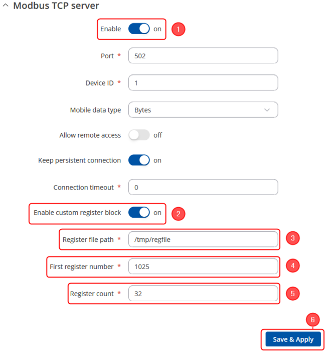
For this example we will be using script to store data into regfile from which then you can read data via Modbus. To achieve follow this steps:
- Enable router to be as Modbus TCP Server (Services -> Modbus -> Modbus TCP Server);
- Enable Custom Register Block in the webUI (Services -> Modbus -> Modbus TCP Server);
- Register file path: tmp/regfile (this is where new register will be stored);
- First register number: 1025 (by default it is 1025 and recommend to keep it, if necessary it could be changed accordantly);
- Register count: 32 (how much "space" there is given for additional Modbus registers, the more register you want to bigger count should be used).
- Save & Apply
Creating Custom Modbus Registers
In order to create custom Modbus register which would allow you to read certain routers information via Modbus, you will need to create a script or any other method for putting certain information into regfile.
Script which would log certain data into Modbus register. To add new script, connect to the device via SSH and use:
$ vi /bin/extramodbus (this script is for this manual purpose, yours might be different)
Insert following script (this script is for this manual purpose, yours might be different) example:
 #!/bin/ash
 while true
 do
 date > /tmp/regfile  #where data will be stored
 df | awk 'NR==3 {print $3}' >> /tmp/regfile
 df | awk 'NR==4 {print $3}' >> /tmp/regfile
 sleep 5
 done
After saving change execution rights with this command:
$ chmod +x /bin/<scriptname> #example: chmod +x /bin/extramodbus
Run the script to start logging data to regfile, to do that simply type in your terminal: <script name> &. For example:
$ extramodbus &
And script will run in the background.
With this script we will be able to get routers local time and couple application values each 5 seconds. Data stored in regfile (cat /tmp/regfile) looks like this:
Wed Jun 17 15:11:29 EEST 2020
69
27
To view collected data in HEX execute this command via SSH:
$hexdump -v /tmp/regfile
0000000 5765 6420 4a75 6e20 3137 2031 353a 3132
0000010 3a32 3020 4545 5354 2032 3032 300a 2d36
0000020 380a 3137 0a00
0000025
Reading Created Custom Modbus Registers with Modbus TCP Client
To read data via Modbus you can use:
- ComTestPro program;
- Modbus TCP Client;
- QModMaster;
Modbus TCP Client configuration
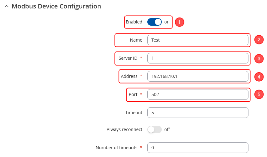
- Add a new Client device by going to your router's WebUI → Services → Modbus → Modbus TCP Client:
- Enable
- Type name
- Write Server ID (1)
- And your Server's (Router's) IP
- Provide the port via which the communication is done
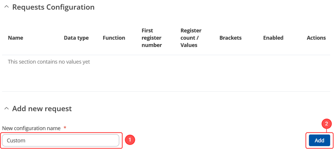
Then scroll down to the Requests Configuration section and add a new request:
- Provide the name for the request
- Click on the Add button
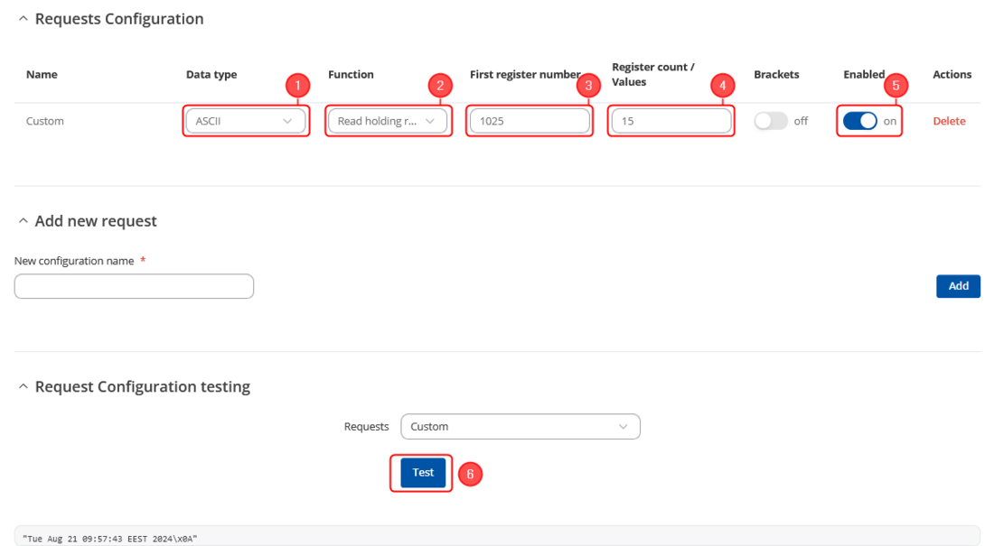
- Select Data type (ASCII)
- Select function (Read holding registers (3))
- Type first register number (1025)
- Type register count (15 in this scenario)
- Enable this request
- With Modbus TCP Client you can read data just by using ASCII data type and interactive test button.
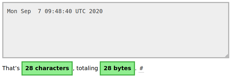
To determine how many registers to specify in the Register count/Values field you should divide character count by two. For example, if you have 28 characters you should input 14 to Register count/Values field.
Reading Created Custom Modbus Registers with QModMaster
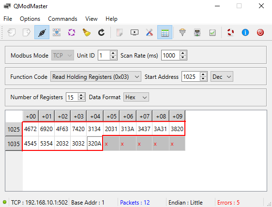
For this example we will be using QModMaster program, which allows us to get Modbus data from device in Hex. So in order to get date from the router by reading custom Modbus registers we need to use following configuration:
- Protocol: Modbus TCP;
- IP Address: 192.168.1.1 (or 192.168.2.1 for TRB1 series) (router's LAN or WAN IP);
- Port: 502 (port number on which Modbus TCP Server is listening);
- Device: 1
- Register: 1025;
- Registers: 15 (register's length).
With this configuration you should get routers date in hex. Below is the example of configuration and what reply we get from the router:
And as you can see we received a reply in hex:
4672 6920 4F63 7420 3134 2031 313A 3437 3A31 3820 4545 5354 2032 3032 320A
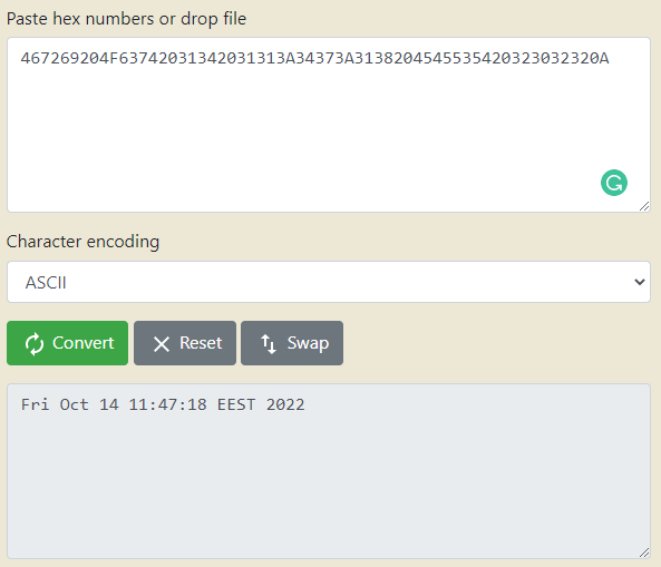
By using certain websites, like this: hex converter we can analyze the data by entering the received hex reply. After conversion we can see the routers date which in ASCII is:
Fri Oct 14 11:47:18 EEST 2022

