Difference between revisions of "Domnev"
| (253 intermediate revisions by the same user not shown) | |||
| Line 1: | Line 1: | ||
| − | + | <p style="color:red">The information on this page is updated in accordance with the [https://wiki.teltonika-networks.com/view/FW_%26_SDK_Downloads'''00.07.08'''] firmware version .</p> | |
| + | __TOC__ | ||
==Summary== | ==Summary== | ||
| − | + | This article contains instructions on how to send M-Bus data to the server using various protocols. | |
| − | ==Configuration overview | + | ==Configuration overview & prerequisites== |
| + | Before we begin, let's take a look at the configuration that we are attempting to achieve and the prerequisites that make it possible. | ||
| − | + | '''Prerequisites''': | |
| + | * TRB143; | ||
| + | * M-Bus device; | ||
| + | * Server; | ||
| + | * An end device (PC, Laptop, Tablet, Smartphone) for configuration; | ||
| − | |||
| − | |||
| − | |||
| − | |||
| − | = | + | {{Template:Networking_rutos_manual_basic_advanced_webui_disclaimer |
| + | | series = RUTX | ||
| + | }} | ||
| − | |||
| − | + | ==Adding M-Bus devices== | |
| − | [[File: | + | To add a new device to the configuration press [[File:Add Button.png|60x90px]] button which is shown below. |
| − | = | + | [[File:Mbus adding new device.png||border|class=tlt-border]] |
| − | === | + | ===Device configuration=== |
---- | ---- | ||
| − | + | You will be granted to a new window. Configure your M-Bus device accordingly: | |
| − | + | ||
| − | + | # '''Name''': Enter the desired name of the M-Bus device | |
| − | + | # '''Address type''': select which M-Bus address will be used | |
| − | + | # '''Primary/Secondary address''': specify M-Bus address | |
| − | + | ||
| − | + | [[File:Mbus adding new device configuration v3.png|border|class=tlt-border]] | |
| + | |||
| + | Test if the M-Bus device is reachable by a specified primary/secondary address. To do so click on [[File:Ping_device_option_mbus.png|110x110px]]. You might get on of two outputs: | ||
| − | [[File: | + | * If you have specified correct primary/secondary address, you will receive: |
| + | [[File:Mbus device pingable v2.png|border|class=tlt-border|300px]] | ||
| − | + | * If you have specified incorrect primary/secondary address, you will receive (if you do not know what address should be used, refer to the Scanning for available M-Bus devices (PRIDET URL) secion: | |
| − | [[File: | + | [[File:Mbus device not pingable v2.png|border|class=tlt-border|300px]] |
| − | + | Once finished, save the configuration by clicking [[File:Savenapply button.png|Savenapply button.png]]. | |
| − | |||
| − | |||
| − | |||
| − | |||
| − | |||
| − | + | ===Scanning for available M-Bus devices=== | |
| − | === | ||
---- | ---- | ||
| − | + | ||
| − | + | If you are not sure what address your M-Bus devices have, you can try scanning for the available M-Bus devices. To do so click on [[File:Scan button.png]] button. | |
| + | |||
| + | ====Scan settings==== | ||
---- | ---- | ||
| − | + | You will be granted to a new window. Configure scan settings accordingly: | |
| − | + | ||
| + | # '''Scan type''': select which M-Bus address will be scanned | ||
| + | # '''Scan range''': From what M-Bus address scanning will start and M-Bus address until scanning will be performed. | ||
| + | [[File:Mbus scan.png|border|class=tlt-border]] | ||
| + | |||
| + | To start the scan click on [[File:Start scan button.png]] button. | ||
| + | |||
| + | ====Found devices==== | ||
---- | ---- | ||
| − | + | Once the scan is finished you should see the list of M-Bus devices that TRB143 were able to find: | |
| − | [[File: | + | |
| + | [[File:Mbus scanned devices add.png|border|class=tlt-border]] | ||
| + | |||
| + | You can either [[File:Pencil2.png]] '''(1)''' M-Bus devices primary address or [[File:Add Button.png|60x90px]] '''(2)''' to the M-Bus devices list. | ||
| + | |||
| + | ==Gathering M-Bus data== | ||
| − | + | If the device successfully added to the list, under the General settings you should see that the Status changes to <span style="color:green">Active</span>. | |
| − | |||
| − | |||
| − | + | [[File:Mbus status active v2.png|border|class=tlt-border]] | |
| − | [[File: | ||
| − | + | ===Data collecting groups=== | |
| − | + | ---- | |
| − | + | To reach data collecting groups configuration press [[File:Pencil2.png]] button. [[File:Add Button.png|60x90px]] button lets you to create a new instance. | |
| − | |||
| − | + | [[File:Mbus data collect overview.png|border|class=tlt-border]] | |
| − | ==== | + | ====Data collecting group instance==== |
---- | ---- | ||
| − | + | Each data collection group contains the following information. Configure device accordingly: | |
| − | # | + | # '''Enabled''': on |
| − | # | + | # '''Name''': desired name of the instance |
| − | + | # '''Period''': desired time duration between data retrievals | |
| + | # '''Data type''': desired data type to process the received data. Depending on your needs you can select between 5 different data types: '''JSON, XML, ASCII, Hexadecimal''' and '''Binary'''. | ||
| − | + | [[File:Mbus data collect group v2.png|border|class=tlt-border]] | |
| − | + | You can check if your configuration works accordingly by pressing the [[File:Mbus test button.png]] button. You should see the data in a pop-up field: | |
| − | |||
| − | |||
| − | [[File: | ||
| − | + | [[File:Mbus TEST output.png|border|class=tlt-border]] | |
| − | |||
| − | === | + | ====Group values==== |
---- | ---- | ||
| − | + | To reach group values configuration press [[File:Pencil2.png]] button: | |
| − | + | ||
| − | + | [[File:Mbus edit group values.png|border|class=tlt-border]] | |
| − | + | There you can adjust additional settings: | |
| − | # | + | # '''Enable''': Enable/disable data group value. |
| − | # ''' | + | # '''FCB toggle''': FCB (Frame Count-Bit), one-bit counter for reliable server-client communication. |
| − | + | # '''Manufacturer information''': Select to include manufacturer information in the payload. | |
| + | # '''Selected parameters''': Select to include the all parameters saved from device, or a custom subset of them. If the custom is selected you can specify '''frame''', '''record''' numbers and also a '''paramater''' | ||
| − | + | [[File:Mbus device groupsa.png|border|class=tlt-border]] | |
| − | = | ||
| − | |||
| − | |||
| − | |||
| − | + | ==Sending data to the server== | |
| − | + | This section contains information on how to send M-Bus data to the server using MQTT and HTTP protocols. | |
| − | |||
| − | |||
| − | |||
| − | |||
| − | === | + | ===Data to Server configuration=== |
---- | ---- | ||
| − | ==== | + | To set up Data to Server, navigate to Services → Data to Server. Enter desired name of the instnace and hit [[File:Add Button.png|60x90px]] button which is shown below. |
| + | |||
| + | [[File:Mbus data to server create.png|border|class=tlt-border]] | ||
| + | |||
| + | ===Data configuration=== | ||
---- | ---- | ||
| − | |||
| − | [[File: | + | [[File:Mbus data to server configuration.png|border|class=tlt-border]] |
| + | |||
| − | + | Once finished configuring Data configuration tab click on [[File:Mbus data to server collection edit.png|160x160px]] button. | |
| − | |||
| − | |||
| − | |||
| − | + | ===Collection configuration=== | |
| − | + | ---- | |
| − | + | [[File:Mbus data to server collection configuration.png|border|class=tlt-border]] | |
| − | + | Once finished configuring Collection configuration tab click on [[File:Mbus data to server server button.png|160x160px]] button. | |
| − | + | ===Server configuration=== | |
| + | ---- | ||
| − | == | + | ====HTTP configuration==== |
| + | ---- | ||
| + | |||
| + | [[File:Mbus data to server HTTP configuration.png|border|class=tlt-border]] | ||
| + | |||
| + | ====MQTT configuration==== | ||
| + | ---- | ||
| + | [[File:Mbus data to server MQTT configuration.png|border|class=tlt-border]] | ||
| − | + | Once finished configuring Server configuration tab click on [[File:Savenapply button.png|Savenapply button.png]] button. | |
| − | |||
| − | + | ==See Also== | |
| − | [ | + | ==External links== |
| + | [https://flespi.io/#/ Flespi.io] | ||
Latest revision as of 09:32, 22 August 2024
The information on this page is updated in accordance with the 00.07.08 firmware version .
Summary
This article contains instructions on how to send M-Bus data to the server using various protocols.
Configuration overview & prerequisites
Before we begin, let's take a look at the configuration that we are attempting to achieve and the prerequisites that make it possible.
Prerequisites:
- TRB143;
- M-Bus device;
- Server;
- An end device (PC, Laptop, Tablet, Smartphone) for configuration;
If you're having trouble finding this page or some of the parameters described here on your device's WebUI, you should turn on "Advanced WebUI" mode. You can do that by clicking the "Advanced" button, located at the top of the WebUI.
Adding M-Bus devices
To add a new device to the configuration press ![]() button which is shown below.
button which is shown below.
Device configuration
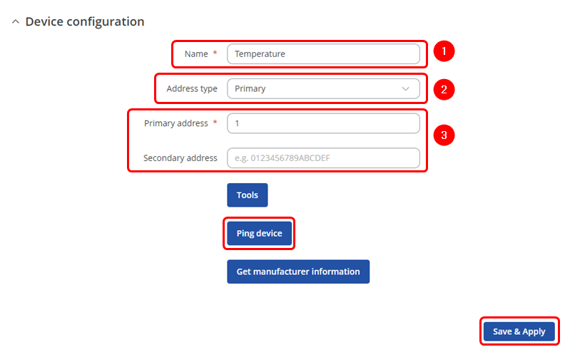
You will be granted to a new window. Configure your M-Bus device accordingly:
- Name: Enter the desired name of the M-Bus device
- Address type: select which M-Bus address will be used
- Primary/Secondary address: specify M-Bus address
Test if the M-Bus device is reachable by a specified primary/secondary address. To do so click on ![]() . You might get on of two outputs:
. You might get on of two outputs:
- If you have specified correct primary/secondary address, you will receive:
- If you have specified incorrect primary/secondary address, you will receive (if you do not know what address should be used, refer to the Scanning for available M-Bus devices (PRIDET URL) secion:
Once finished, save the configuration by clicking ![]() .
.
Scanning for available M-Bus devices
If you are not sure what address your M-Bus devices have, you can try scanning for the available M-Bus devices. To do so click on ![]() button.
button.
Scan settings
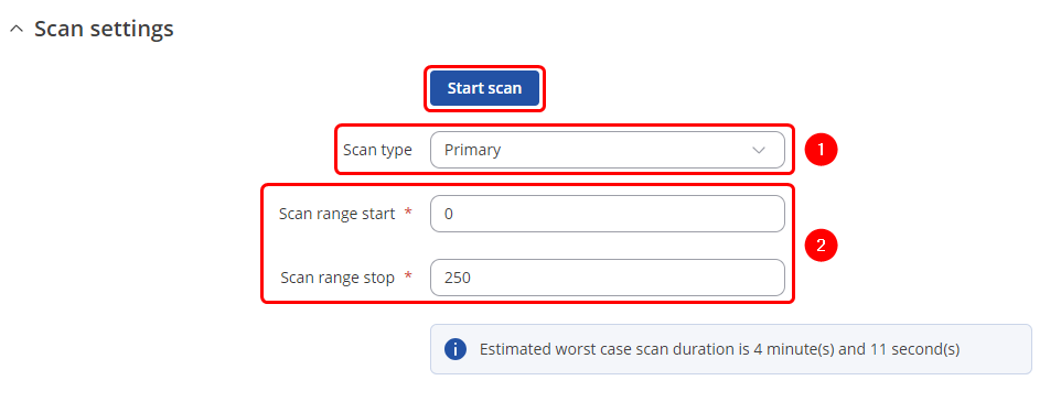
You will be granted to a new window. Configure scan settings accordingly:
- Scan type: select which M-Bus address will be scanned
- Scan range: From what M-Bus address scanning will start and M-Bus address until scanning will be performed.
To start the scan click on ![]() button.
button.
Found devices
Once the scan is finished you should see the list of M-Bus devices that TRB143 were able to find:
You can either ![]() (1) M-Bus devices primary address or
(1) M-Bus devices primary address or ![]() (2) to the M-Bus devices list.
(2) to the M-Bus devices list.
Gathering M-Bus data
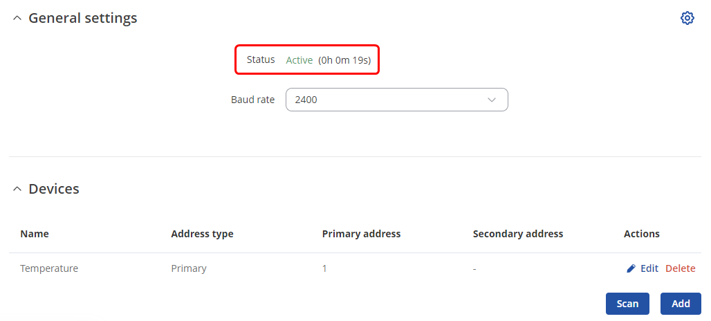
If the device successfully added to the list, under the General settings you should see that the Status changes to Active.
Data collecting groups
To reach data collecting groups configuration press ![]() button.
button. ![]() button lets you to create a new instance.
button lets you to create a new instance.
Data collecting group instance
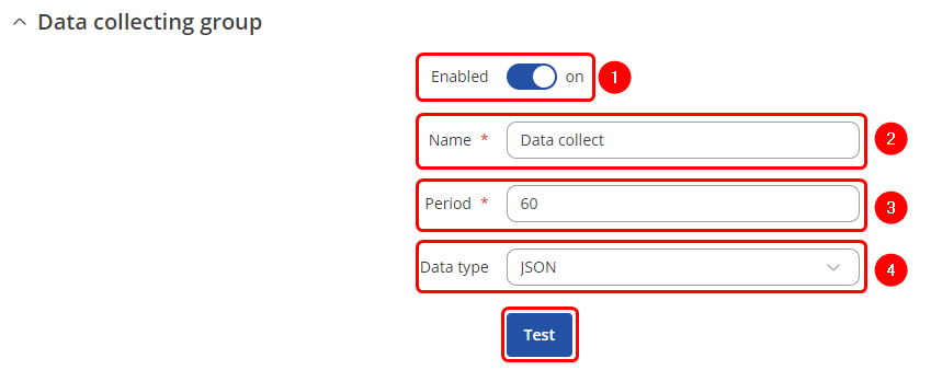
Each data collection group contains the following information. Configure device accordingly:
- Enabled: on
- Name: desired name of the instance
- Period: desired time duration between data retrievals
- Data type: desired data type to process the received data. Depending on your needs you can select between 5 different data types: JSON, XML, ASCII, Hexadecimal and Binary.
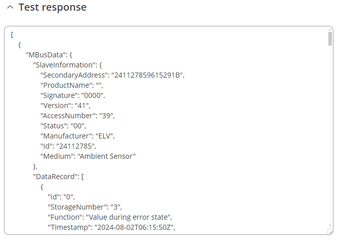
You can check if your configuration works accordingly by pressing the ![]() button. You should see the data in a pop-up field:
button. You should see the data in a pop-up field:
Group values
To reach group values configuration press ![]() button:
button:
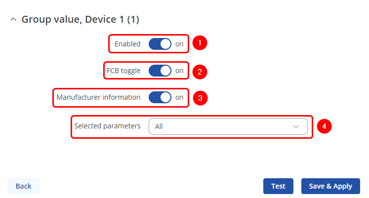
There you can adjust additional settings:
- Enable: Enable/disable data group value.
- FCB toggle: FCB (Frame Count-Bit), one-bit counter for reliable server-client communication.
- Manufacturer information: Select to include manufacturer information in the payload.
- Selected parameters: Select to include the all parameters saved from device, or a custom subset of them. If the custom is selected you can specify frame, record numbers and also a paramater
Sending data to the server
This section contains information on how to send M-Bus data to the server using MQTT and HTTP protocols.
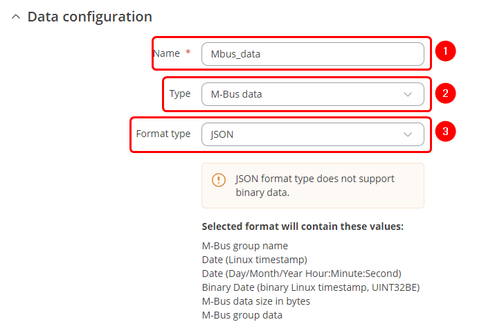
Data to Server configuration
To set up Data to Server, navigate to Services → Data to Server. Enter desired name of the instnace and hit ![]() button which is shown below.
button which is shown below.
Data configuration
Once finished configuring Data configuration tab click on ![]() button.
button.
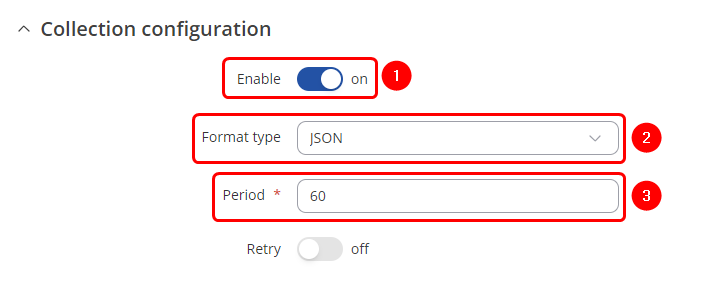
Collection configuration
Once finished configuring Collection configuration tab click on ![]() button.
button.
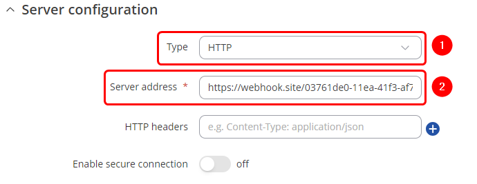
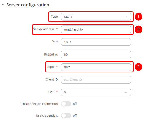
Server configuration
HTTP configuration
MQTT configuration
Once finished configuring Server configuration tab click on ![]() button.
button.


