Domnev1: Difference between revisions
No edit summary |
No edit summary |
||
| (18 intermediate revisions by the same user not shown) | |||
| Line 1: | Line 1: | ||
<p style="color:red">The information | <p style="color:red">The information on this page is updated in accordance with the [https://wiki.teltonika-networks.com/view/FW_%26_SDK_Downloads'''00.07.09'''] firmware version .</p> | ||
==Introduction== | ==Introduction== | ||
This article contains step-by-step instructions on how to set up bidirectional communication between two serial RS232 devices over TCP/IP. | |||
=== | ==Configuration overview & prerequisites== | ||
End devices are connected to separate RUT956 routers through RS232 connection, and client connects to the server through its Public IP address. | |||
[[File: | [[File:OverIP Client Server network topology.png|border|class=tlt-border|1005px]] | ||
'''Prerequisites''': | |||
*Two devices with RS232 support | |||
*Two end devices (PCs or RS232 devices able to send and receive data, here we will be using PCs with serial simulators) | |||
*Over IP Server must have a SIM card with a Public Static or Public Dynamic IP address (more on IP address types here) to make remote access possible | |||
{{Template:Networking_rutos_manual_basic_advanced_webui_disclaimer | |||
| series = RUTX | |||
}} | |||
==Over IP Server== | |||
====Obtaining Public IP: Set an APN==== | |||
---- | |||
In this example we are using Public IPs, it also works with Private IPs if routers are in same LAN | |||
'''Note:''' If you have a Public IP address already, you can skip this step. | |||
To set the APN, while in the router's WebUI, navigate to the '''Network → Mobile → General → Interface mob1s1a1 APN configuration''': | |||
== | [[File:Set APN PF.png|border|class=tlt-border|alt=]] | ||
Once in the '''Interface mob1s1a1 APN configuration''' window, edit your mobile interface, find the '''APN''' field and enter you Internet Service Provider's APN: | |||
# '''Disable the Auto APN option''' | |||
# Choose the correct '''APN''', which gives out a public IP address (for more information about that contact your Internet Service Provider) | |||
= | [[File:Set APN PF APN selected.png|border|class=tlt-border]] | ||
Additional notes on APN: | |||
* '''NOTE 1''': don't use the exact APN value as seen in the example above as it will not work with your SIM card. APN depends on your Internet Service Provider (ISP), therefore, your ISP should provide you with their APN or, in many case, you can find your ISP's APN with an online search. | |||
* '''NOTE 2''': furthermore, it should be noted that not all SIM cards support this functionality. Static or Dynamic Public IP addresses (obtained through APN) are a paid service and setting any APN value for a SIM card that doesn't support this service will most likely result in losing your data connection. If this is the case, it can be fixed by simply deleting the APN, but it also means that remote access through mobile WAN IP will most likely not work on your SIM card. | |||
* '''NOTE 3''': in some cases the SIM card doesn't require an APN in order to obtain a Public IP address. If that is the case for you, simply check what your router's mobile WAN IP address is - if it's already a Public IP address, then you don't need to set an APN. The easiest way to find what your mobile WAN IP address is to log in to the router's WebUI and check the '''MOB1S1A1''' widget in the '''Overview''' page: | |||
[[File:Where public IP.png|border|class=tlt-border]] | |||
===Over IP Server RS232 configuration=== | |||
---- | |||
Navigate to the Over IP tab by going to '''Services → Serial Utilities → Over IP''' . Insert desired name and select RS232. Make sure to '''enable the instance''' '''(1)''' and '''configure Serial port in accordance''' '''(2)''' to connected device, these should match on both routers to avoid miscommunication. | |||
[[File:OverIP Sever serial config.png|border|class=tlt-border]] | |||
===Over IP Server configuration=== | |||
---- | |||
After applying RS232 configuration scroll down and configure Over IP Server: | |||
# Mode '''Server'''- the device waits for incoming connections. | |||
# Select a desired protocol, '''TCP or UDP'''. | |||
# '''TCP/UDP port''' - specify desired port. | |||
[[File:OverIP TCP server configuration port.png|border|class=tlt-border]] | |||
===IP Filter=== | |||
---- | |||
Once finished the above configuration, add interfaces through which routers will be communicating, You can add IP address that will be allowed to connect or enter 0.0.0.0 to allow all connections coming through correct port. | |||
[[File:OverIP TPC Server IP filter.png|border|class=tlt-border]] | |||
==OverIP Client== | |||
=== | ===OverIP Server RS232 configuration=== | ||
---- | ---- | ||
Navigate to the OverIP tab by going to '''Services → Serial Utilities → OverIP''' . Insert desired name and select RS232. Make sure to '''enable the instance''' '''(1)''' and '''configure Serial port in accordance''' '''(2)''' to connected device, these should match on both routers to avoid miscommunication. | |||
[[File:OverIP Client serial config.png|border|class=tlt-border]] | |||
=== | ===OverIP Client configuration=== | ||
---- | ---- | ||
After applying RS232 configuration scroll down and configure Over IP Server: | |||
# Mode '''Client''' – the device initiates the connection. | |||
# Select a desired protocol, '''TCP or UDP'''. | |||
# '''Address''' is the Over IP Sever Public IP address. '''Port''' is the port we have configured on the Over IP Server device. | |||
[[File:OverIP TCP Client configuration IP port.png|border|class=tlt-border]] | |||
== | ==Testing configuration== | ||
If you followed configuration steps both end devices should be able to send and receive data. In this example we use Hercules program on both computers and open serial communication with routers. We are able to send and receive data through RS232. | |||
[[File:Over IP Client Server hercules test.png|border|class=tlt-border|1004px]] | |||
Latest revision as of 20:49, 13 October 2024
The information on this page is updated in accordance with the 00.07.09 firmware version .
Introduction
This article contains step-by-step instructions on how to set up bidirectional communication between two serial RS232 devices over TCP/IP.
Configuration overview & prerequisites
End devices are connected to separate RUT956 routers through RS232 connection, and client connects to the server through its Public IP address.
Prerequisites:
- Two devices with RS232 support
- Two end devices (PCs or RS232 devices able to send and receive data, here we will be using PCs with serial simulators)
- Over IP Server must have a SIM card with a Public Static or Public Dynamic IP address (more on IP address types here) to make remote access possible
If you're having trouble finding this page or some of the parameters described here on your device's WebUI, you should turn on "Advanced WebUI" mode. You can do that by clicking the "Advanced" button, located at the top of the WebUI.
Over IP Server
Obtaining Public IP: Set an APN
In this example we are using Public IPs, it also works with Private IPs if routers are in same LAN
Note: If you have a Public IP address already, you can skip this step.
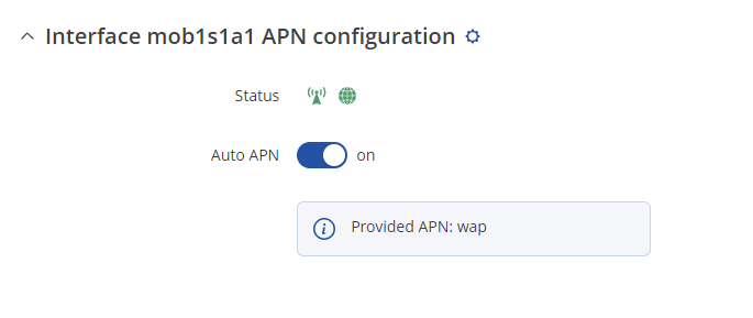
To set the APN, while in the router's WebUI, navigate to the Network → Mobile → General → Interface mob1s1a1 APN configuration:
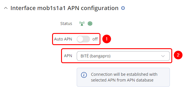
Once in the Interface mob1s1a1 APN configuration window, edit your mobile interface, find the APN field and enter you Internet Service Provider's APN:
- Disable the Auto APN option
- Choose the correct APN, which gives out a public IP address (for more information about that contact your Internet Service Provider)
Additional notes on APN:
- NOTE 1: don't use the exact APN value as seen in the example above as it will not work with your SIM card. APN depends on your Internet Service Provider (ISP), therefore, your ISP should provide you with their APN or, in many case, you can find your ISP's APN with an online search.
- NOTE 2: furthermore, it should be noted that not all SIM cards support this functionality. Static or Dynamic Public IP addresses (obtained through APN) are a paid service and setting any APN value for a SIM card that doesn't support this service will most likely result in losing your data connection. If this is the case, it can be fixed by simply deleting the APN, but it also means that remote access through mobile WAN IP will most likely not work on your SIM card.
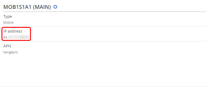
- NOTE 3: in some cases the SIM card doesn't require an APN in order to obtain a Public IP address. If that is the case for you, simply check what your router's mobile WAN IP address is - if it's already a Public IP address, then you don't need to set an APN. The easiest way to find what your mobile WAN IP address is to log in to the router's WebUI and check the MOB1S1A1 widget in the Overview page:
Over IP Server RS232 configuration
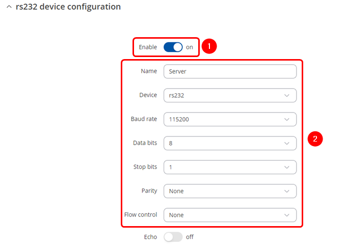
Navigate to the Over IP tab by going to Services → Serial Utilities → Over IP . Insert desired name and select RS232. Make sure to enable the instance (1) and configure Serial port in accordance (2) to connected device, these should match on both routers to avoid miscommunication.
Over IP Server configuration
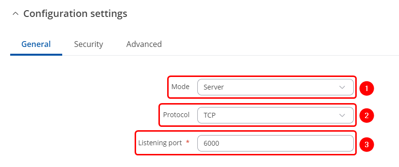
After applying RS232 configuration scroll down and configure Over IP Server:
- Mode Server- the device waits for incoming connections.
- Select a desired protocol, TCP or UDP.
- TCP/UDP port - specify desired port.
IP Filter
Once finished the above configuration, add interfaces through which routers will be communicating, You can add IP address that will be allowed to connect or enter 0.0.0.0 to allow all connections coming through correct port.
OverIP Client
OverIP Server RS232 configuration
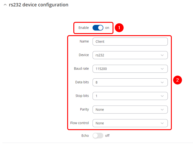
Navigate to the OverIP tab by going to Services → Serial Utilities → OverIP . Insert desired name and select RS232. Make sure to enable the instance (1) and configure Serial port in accordance (2) to connected device, these should match on both routers to avoid miscommunication.
OverIP Client configuration
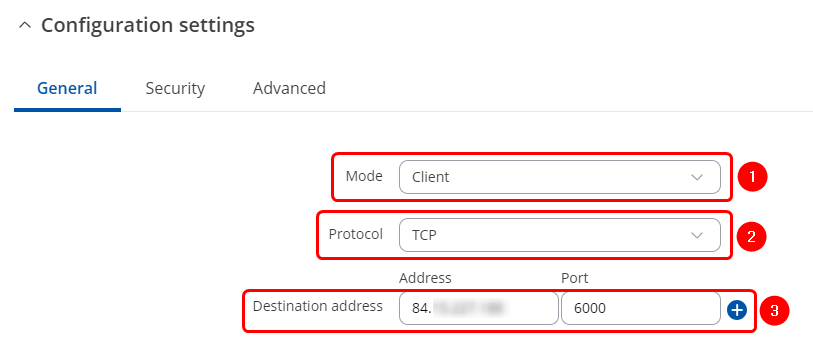
After applying RS232 configuration scroll down and configure Over IP Server:
- Mode Client – the device initiates the connection.
- Select a desired protocol, TCP or UDP.
- Address is the Over IP Sever Public IP address. Port is the port we have configured on the Over IP Server device.
Testing configuration
If you followed configuration steps both end devices should be able to send and receive data. In this example we use Hercules program on both computers and open serial communication with routers. We are able to send and receive data through RS232.


