Difference between revisions of "TRM240 First Start"
Gytispieze (talk | contribs) m (Text replacement - "utilixation" to "utilization") |
(Created page with "{{Template: Networking_device_first_start | name = RUTX08 | series = RUTXxx | short_description = RUTX08 Ethernet Router | file_device = Rutx08_h...") |
||
| (40 intermediate revisions by 2 users not shown) | |||
| Line 1: | Line 1: | ||
| − | + | {{Template: Networking_device_first_start | |
| − | + | | name = RUTX08 | |
| − | + | | series = RUTXxx | |
| − | + | | short_description = RUTX08 Ethernet Router | |
| − | + | | file_device = Rutx08_hd_2_demo.jpg | |
| − | + | | size_device = 250 | |
| − | + | | file_front = Networking_rutx08_manual_panels_front_v1.jpg | |
| − | + | | size_front = 400 | |
| − | + | | file_back = Networking_rutx08_manual_panels_back_v1.jpg | |
| − | + | | size_back = 400 | |
| − | + | }} | |
| − | |||
| − | |||
| − | |||
| − | |||
| − | |||
| − | |||
| − | |||
| − | |||
| − | |||
| − | |||
| − | |||
| − | |||
| − | |||
| − | |||
| − | |||
| − | |||
| − | |||
| − | |||
| − | |||
| − | |||
| − | |||
| − | |||
| − | |||
| − | |||
| − | |||
| − | |||
| − | |||
| − | |||
| − | |||
| − | |||
| − | |||
| − | |||
| − | |||
| − | |||
| − | |||
| − | |||
| − | |||
| − | |||
| − | |||
| − | |||
| − | |||
| − | |||
| − | |||
| − | |||
| − | |||
| − | |||
| − | |||
| − | |||
| − | |||
| − | |||
| − | |||
| − | |||
| − | |||
| − | |||
| − | |||
| − | |||
| − | |||
| − | |||
| − | |||
| − | |||
| − | |||
| − | |||
| − | |||
| − | |||
| − | |||
| − | |||
| − | |||
| − | |||
| − | |||
| − | |||
| − | |||
| − | |||
| − | |||
| − | |||
| − | |||
| − | |||
| − | |||
| − | |||
| − | |||
| − | |||
| − | |||
| − | |||
| − | |||
| − | |||
| − | |||
| − | |||
| − | |||
| − | |||
| − | |||
| − | |||
| − | |||
| − | |||
| − | |||
| − | |||
| − | |||
| − | |||
| − | | | ||
| − | |||
| − | | | ||
| − | |||
| − | | | ||
| − | | | ||
| − | |||
| − | | | ||
| − | | | ||
| − | |||
| − | | | ||
| − | |||
| − | |||
| − | |||
| − | |||
| − | |||
| − | |||
| − | |||
| − | |||
| − | |||
| − | |||
| − | |||
| − | |||
| − | |||
Revision as of 14:04, 20 November 2019
Main Page > TRM Modems > TRM240 > TRM240 First StartThis Wiki page contains the online version of the Quick Start Guide (QSG) for the RUTX08 Ethernet Router. Here you will find an overview of the various components found on the front and back sides of a RUTX08 device, basic hardware installation, first login information, device specifications and general safety information. It is highly recommended that you acquaint yourself with with the Quick Start Guide before using the device. If you own a RUTX08 device, you can also find a printed version of the Quick Start Guide in the device's package.

Front view
|
 |
Back view
|
 |
Connectors
|
 |
||||||||||||||||||
Configure your computer (Windows)
- Power up RUTX08 and connect one LAN cable (included in a box) end to RUTX08 Ethernet port and other to your computer.
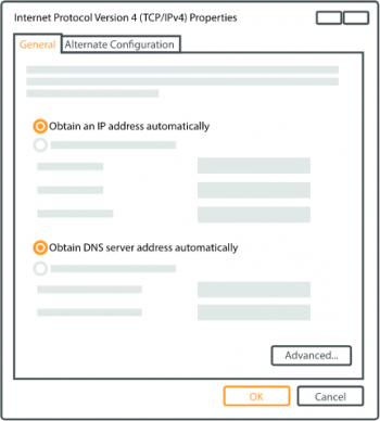
- Setup Ethernet network adapter on your computer (right click on Ethernet Network Connection and select Properties. After that select Internet Protocol Version 4 (TCP/IP) and click Properties).
- Select Obtain IP address and Obtain DNS server address automatically if they are not selected. Click OK.

Login to device
- To enter the router's Web interface (WebUI), type http://192.168.1.1 into the URL field of your Internet browser.
- Use the following login information when prompted for authentication:
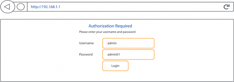
- After you login, you will be prompted to change your password for security reasons. The new password must contain at least 8 characters, including at least one uppercase letter, one lowercase letter and one digit. This step is mandatory and you will not be able to interact with the router's WebUI before you change the password.
- When you change the router's password, the Configuration Wizard will start. The Configuration Wizard is a tool used to setup some of the router's main operating parameters.

Safety information
The RUTX08 router must be used in compliance with any and all applicable national and international laws and with any special restrictions regulating the utilization of the communication module in prescribed applications and environments.
| Bundled accessories specifications | |
|---|---|
| Power | AC/DC power adapter 12 V 1.5 A, 4 pin plug |
![]() This sign on the package means that is necessary to read the User's Manual before you start using the device.
This sign on the package means that is necessary to read the User's Manual before you start using the device.
 This sign on the package means that all used electronic and electric equipment should not be mixed with general household waste.

