Load Balancing Rules/Policies examples: Difference between revisions
No edit summary |
|||
| (16 intermediate revisions by 2 users not shown) | |||
| Line 1: | Line 1: | ||
<p style="color:red">The information in this page is updated in accordance with [https://wiki.teltonika-networks.com/view/FW_%26_SDK_Downloads'''00.07.08'''] firmware version.</p> | |||
==Introduction== | ==Introduction== | ||
| Line 11: | Line 12: | ||
Both Load Balancing and Failover cannot be used at the same time. If you wish to select Load Balancing, you can do that in the dropdown located in the top-right corner of the page: | Both Load Balancing and Failover cannot be used at the same time. If you wish to select Load Balancing, you can do that in the dropdown located in the top-right corner of the page: | ||
[[File: | [[File:RutOS_Load_Balancing_rules_policies_7.8_load_balancing_enable.png|border|class=tlt-border|1100px]] | ||
Do not forget to enable the load balancing interfaces accordingly, so the policies would work, in first example we will need mob1s1a1 and mob2s1a1: | |||
[[File:RutOS_Load_Balancing_rules_policies_7.8_load_balancing_enable_instances.png|border|class=tlt-border|1100px]] | |||
If you're having trouble finding this page or some of the parameters described here on your device's WebUI, you should '''turn on "Advanced WebUI" mode'''. You can do that by clicking the "Basic" button under "Mode", which is located at the top-right corner of the WebUI. | If you're having trouble finding this page or some of the parameters described here on your device's WebUI, you should '''turn on "Advanced WebUI" mode'''. You can do that by clicking the "Basic" button under "Mode", which is located at the top-right corner of the WebUI. | ||
[[File: | [[File:Networking_rutos_manual_webui_basic_advanced_mode_75.gif|border|center|class=tlt-border|1102x93px]] | ||
==Prerequisites== | ==Prerequisites== | ||
| Line 26: | Line 30: | ||
==Preparation== | ==Preparation== | ||
As mentioned in Prerequisites, you will need to configure a VLAN on the RUT device, detailed instructions on how to configure it can be found on this page: '''[[VLAN Set Up]]''' | As mentioned in Prerequisites, you will need to configure a VLAN on the RUT device, detailed instructions on how to configure it can be found on this page: '''[[VLAN Set Up]]''' | ||
Everything else we will configure along the way. | Everything else we will configure along the way. | ||
===Topology=== | ===Topology=== | ||
---- | |||
[[File:Networking rutxxx configuration examples load balancing topology v1.png|border|class=tlt-border|1100px]] | |||
==Configurating RUTX12 device== | ==Configurating RUTX12 device== | ||
We will start with the RUTX12 configuration. We will configure '''RUTX12''' traffic from '''LAN''' port 1 to go through '''SIM1''' and traffic from '''LAN''' port 2 to go through '''SIM2'''. To complete this configuration you will require to have '''one VLAN configurated already'''. Let's begin by navigating to your device's '''WebUI → Network → Failover → Multiwan'''. On this page you will need to configure two new rules, to do so at the bottom you can find the '''ADD NEW INSTANCE''' section, where input the name for a rule and press the button '''ADD'''. | |||
[[File:RutOS_Load_Balancing_rules_policies_7.8_load_balancing_new_instance.png|border|class=tlt-border|1100px]] | |||
===Policy configuration=== | |||
---- | ---- | ||
Firstly we will need to create new policies, via which the interface will be routed, for that we will need to create 2 new load balancing Policies: | |||
* '''First policy''' - Will be used to route '''LAN1''' network via '''mob1s1a1''' interface. | |||
* '''Second policy''' - Will be used to route '''LAN2''' network via '''mob2s1a1''' interface. | |||
[[File: | [[File:RutOS_Load_Balancing_rules_policies_7.8_load_balancing_new_policy.png|border|class=tlt-border]] | ||
===LAN1 configuration=== | |||
---- | |||
* '''Source address''' - input your '''LAN''' network address in this example '''192.168.1.0/24''' | |||
* '''Destination address''' - leave '''0.0.0.0/0''' here, since we want to use this rule when navigating '''anywhere''' from '''LAN1''' port | |||
* '''Policy assigned''' - pick the policy on which you have set up for '''mob1s1a1''' | |||
[[File:RutOS_Load_Balancing_rules_policies_7.8_load_balancing_rule1.png|border|class=tlt-border|1100px]] | |||
After setting everything up Save the configuration. | |||
===LAN2 configuration=== | |||
In the topology, you can see that the second '''LAN''' port has an IP of '''192.168.3.0/24''', we will configure the first rule accordingly for this port. | |||
---- | |||
* '''Source address''' - input your '''VLAN''' network address in this example '''192.168.3.0/24''' | * '''Source address''' - input your '''VLAN''' network address in this example '''192.168.3.0/24''' | ||
* '''Destination address''' - leave '''0.0.0.0/0''' here, since we want to use this rule when navigating '''anywhere''' from '''LAN2''' port | * '''Destination address''' - leave '''0.0.0.0/0''' here, since we want to use this rule when navigating '''anywhere''' from '''LAN2''' port | ||
* '''Policy assigned''' - pick the policy on which you have set up for '''mob1s2a1''' | * '''Policy assigned''' - pick the policy on which you have set up for '''mob1s2a1''' | ||
[[File:RutOS_Load_Balancing_rules_policies_7.8_load_balancing_rule2.png|border|class=tlt-border|1100px]] | |||
After setting everything up Save the configuration. | |||
''Note - Do not forget to '''Enable''' the Load Balancing for '''mob1s1a1''' and '''mob1s2a1''' interfaces.'' | |||
For RUTX12 the configuration is finished, if you are not planning to configure another device (with one modem) skip to the '''Testing the Configuration''' section. | |||
---- | |||
Overall our rules should look like this: | |||
[[File:RutOS_Load_Balancing_rules_policies_7.8_load_balancing_rules_overall.png|border|class=tlt-border|1100px]] | |||
==Configurating Device with one modem== | |||
In this section, we will configure a device unlike '''RUTX12''' with one modem. We will configure all of the traffic from the '''LAN1''' port to go through '''SIM1''' and all of the traffic from the '''LAN2''' port will go through WiFi WAN (you can use regular Wired WAN instead). | |||
Once again we will start the configuration by '''configuring''' '''LAN2''' port traffic, keep in mind that the '''LAN2''' port is configurated as '''VLAN 192.168.3.0/24'''. | |||
===Policy configuration=== | |||
---- | |||
Firstly we will need to create new policies, via which the interface will be routed, for that we will need to create 2 new load balancing Policies: | |||
* '''First policy''' - Will be used to route '''LAN1''' network via '''Wireless WAN''' or '''Wired WAN''' interface. | |||
* '''Second policy''' - Will be used to route '''LAN2''' network via '''mob2s1a1''' interface. | |||
---- | |||
[[File:RutOS_Load_Balancing_rules_policies_7.8_load_balancing_new_policy_2.png|border|class=tlt-border]] | |||
===LAN1 configuration=== | |||
---- | |||
* '''Source address''' - input your '''LAN''' network address in this example '''192.168.1.0/24''' | |||
* '''Destination address''' - leave '''0.0.0.0/0''' here, since we want to use this rule when navigating '''anywhere''' from '''LAN1''' port | |||
* '''Policy assigned''' - pick the policy on which you have set up for '''Wireless WAN''' or '''Wired WAN'''. | |||
[[File:RutOS_Load_Balancing_rules_policies_7.8_load_balancing_rule1.png|border|class=tlt-border|1100px]] | |||
After setting everything up Save the configuration. | |||
===LAN2 configuration=== | |||
---- | |||
* '''Source address''' - input your '''VLAN''' network address in this example '''192.168.3.0/24''' | |||
* '''Destination address''' - leave '''0.0.0.0/0''' here, since we want to use this rule when navigating '''anywhere''' from '''LAN2''' port | |||
* '''Policy assigned''' - pick the policy on which you have set up for '''mob2s1a1''' | |||
[[File:RutOS_Load_Balancing_rules_policies_7.8_load_balancing_rule2.png|border|class=tlt-border|1100px]] | |||
After setting everything up Save the configuration. | After setting everything up Save the configuration. | ||
''Note - Do not forget to '''Enable''' the Load Balancing for '''mob1s1a1''' and '''Wireless WAN/Wired WAN''' interfaces.'' | |||
---- | |||
Overall our rules should look like this: | |||
[[File:RutOS_Load_Balancing_rules_policies_7.8_load_balancing_rules_overall.png|border|class=tlt-border|1100px]] | |||
==Testing Configuration== | |||
In order to test if the configuration if it's working we will use TCP Dump, TCP Dump will let us capture traffic that goes through each interface of the device. | |||
===Installing TCP Dump on RUT=== | |||
---- | ---- | ||
=== | Firstly, you will need to connect to the '''RUT''' device's '''CLI/SSH'''. You can connect the '''RUT''' device CLI via WebUI by navigating to '''Services → CLI'''. Log in to '''CLI''' with the user name '''root''' and the router's admin password. | ||
Now execute these commands one at a time: | |||
''opkg update'' | |||
''opkg install tcpdump'' | |||
To test if TCP Dump has been installed on your device execute the command ''tcpdump'' | |||
===Testing the configuration via TCPDUMP=== | |||
---- | |||
The simplest way to test the configuration via '''tcpdump''' would be to use two commands from the same device. The first one would be ping to google DNS (from 192.168.1.1 and 192.168.3.1 IPs) and the other would be to '''tcpdump''' the correct interface. I will be using the setup of '''Configurating RUTX12 device''' for this example, testing devices with one modem is almost identical. | |||
We will do this by opening two instances of your device's '''CLI/SSH''', to access it, login to one of the routers' WebUI and navigate to '''Services → CLI'''. Log in to CLI with the user name '''root''' and the router's admin password (Open two instances of CLI). | |||
In the first instance, we will let the ping command which will send ICMP requests to '''8.8.8.8''' from '''192.168.1.1(LAN IP)'''. The command for this will be used: '''''ping -I 192.168.1.1 8.8.8.8''''' | |||
On the second instance, we will run TCPDUMP on interface '''wwan0''' to capture if packets are coming through '''Mobile WAN'''. The command for this will be used: '''''tcpdump -i wwan0 icmp -n''''' | |||
We will also only look at ICMP requests since the Mobile will have a lot of different packets coming in and out. | |||
====Output of Ping command==== | |||
---- | |||
[[File:Networking rut configuration mwan ping v1.jpg|border|class=tlt-border|1100px]] | |||
== | ====Output of TCPDUMP command==== | ||
---- | |||
[[File:Networking rut configuration mwan tcpdump v2.jpg|border|class=tlt-border|1100px]] | |||
You should see in the '''tcpdump''' output that we have ICMP requests going out of the '''WWAN0''' interface, this means that the configuration is working, and '''192.168.1.1/24''' interface traffic goes through the correct interface, you should also test this on another SIM card(interface). | |||
You can also stop the ping on your device and you should see that '''ICMP''' requests stop appearing in the '''tcpdump''' output. | |||
[[Category:Router control and monitoring]] | |||
Latest revision as of 13:38, 29 July 2024
Main Page > General Information > Configuration Examples > Router control and monitoring > Load Balancing Rules/Policies examplesThe information in this page is updated in accordance with 00.07.08 firmware version.
Introduction
In this example, we will examine Load Balancing rules and policies and we will set up rules where all traffic from one LAN port will be going through the Mobile interface and all the traffic from the second port will be going through the Wireless WAN/Wired WAN or the Second Sim card (if used with RUTX12).
Load Balancing is a method of dividing traffic between multiple WAN interfaces. Load Balancing can be used to share the data load between different interfaces and increase the overall Internet speed for multiple users and connections. It is important to note that Load Balancing does not increase speed for any single connection. For example, if you're downloading a large file, using Load Balancing will not increase the speed of that download.
However, Load Balancing can be used to increase the speed of multiple connections. For example, when used in a WiFi network, Load Balancing would utilize the resources of multiple WAN interfaces to handle the many various requests of different clients.
Both Load Balancing and Failover cannot be used at the same time. If you wish to select Load Balancing, you can do that in the dropdown located in the top-right corner of the page:
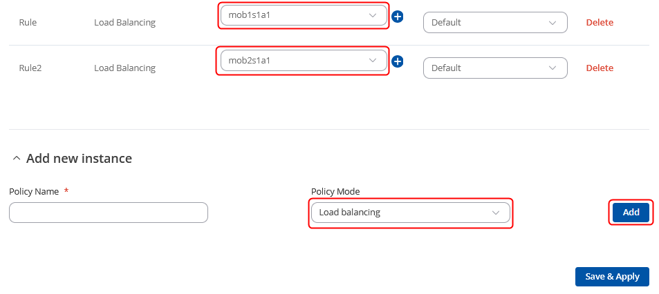
Do not forget to enable the load balancing interfaces accordingly, so the policies would work, in first example we will need mob1s1a1 and mob2s1a1:
If you're having trouble finding this page or some of the parameters described here on your device's WebUI, you should turn on "Advanced WebUI" mode. You can do that by clicking the "Basic" button under "Mode", which is located at the top-right corner of the WebUI.

Prerequisites
- RUTX12 device or any other RUT device
- 2 SIM cards or other WAN alternatives (WiFi WAN or regular LAN cable connected to WAN port)
- At least one end device (PC, Laptop, Tablet, Smartphone) to configure the routers
- At least one VLAN configurated on a device
Preparation
As mentioned in Prerequisites, you will need to configure a VLAN on the RUT device, detailed instructions on how to configure it can be found on this page: VLAN Set Up Everything else we will configure along the way.
Topology
Configurating RUTX12 device
We will start with the RUTX12 configuration. We will configure RUTX12 traffic from LAN port 1 to go through SIM1 and traffic from LAN port 2 to go through SIM2. To complete this configuration you will require to have one VLAN configurated already. Let's begin by navigating to your device's WebUI → Network → Failover → Multiwan. On this page you will need to configure two new rules, to do so at the bottom you can find the ADD NEW INSTANCE section, where input the name for a rule and press the button ADD.
Policy configuration
Firstly we will need to create new policies, via which the interface will be routed, for that we will need to create 2 new load balancing Policies:
- First policy - Will be used to route LAN1 network via mob1s1a1 interface.
- Second policy - Will be used to route LAN2 network via mob2s1a1 interface.
LAN1 configuration
- Source address - input your LAN network address in this example 192.168.1.0/24
- Destination address - leave 0.0.0.0/0 here, since we want to use this rule when navigating anywhere from LAN1 port
- Policy assigned - pick the policy on which you have set up for mob1s1a1
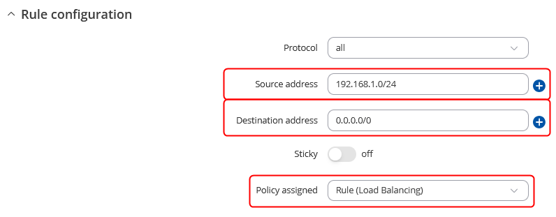 After setting everything up Save the configuration.
LAN2 configuration
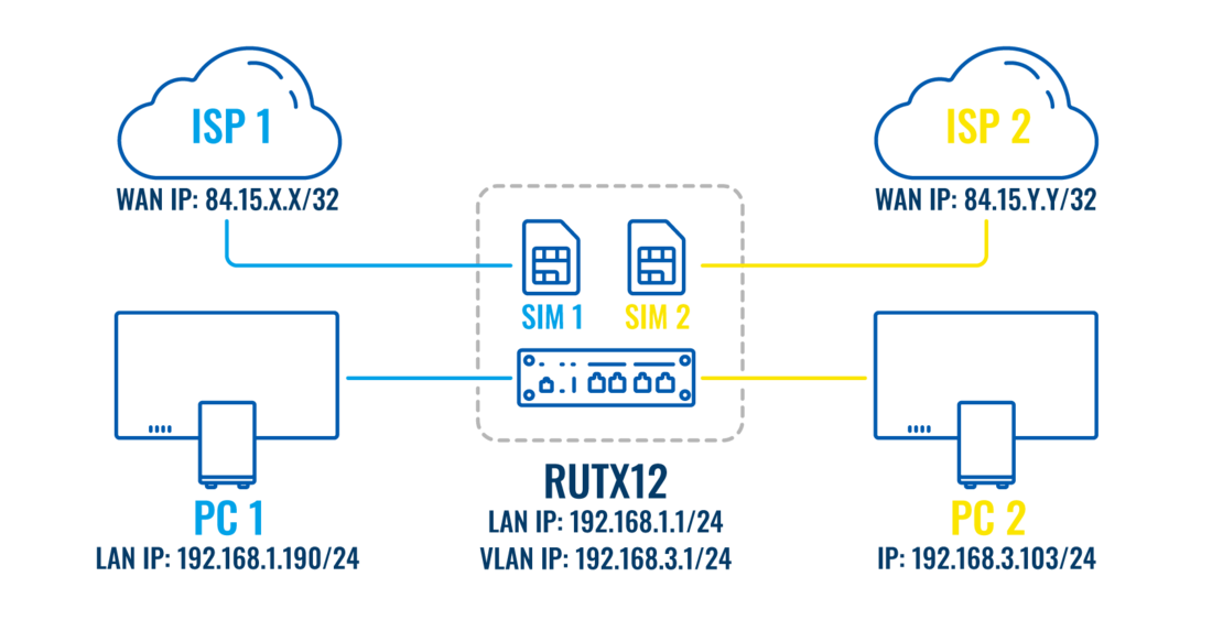
In the topology, you can see that the second LAN port has an IP of 192.168.3.0/24, we will configure the first rule accordingly for this port.
- Source address - input your VLAN network address in this example 192.168.3.0/24
- Destination address - leave 0.0.0.0/0 here, since we want to use this rule when navigating anywhere from LAN2 port
- Policy assigned - pick the policy on which you have set up for mob1s2a1
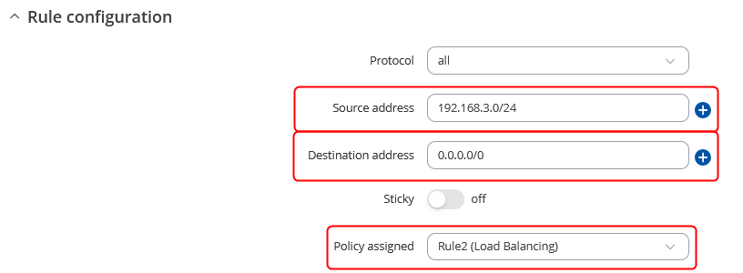 After setting everything up Save the configuration.
Note - Do not forget to Enable the Load Balancing for mob1s1a1 and mob1s2a1 interfaces.
For RUTX12 the configuration is finished, if you are not planning to configure another device (with one modem) skip to the Testing the Configuration section.
Overall our rules should look like this:

Configurating Device with one modem
In this section, we will configure a device unlike RUTX12 with one modem. We will configure all of the traffic from the LAN1 port to go through SIM1 and all of the traffic from the LAN2 port will go through WiFi WAN (you can use regular Wired WAN instead). Once again we will start the configuration by configuring LAN2 port traffic, keep in mind that the LAN2 port is configurated as VLAN 192.168.3.0/24.
Policy configuration
Firstly we will need to create new policies, via which the interface will be routed, for that we will need to create 2 new load balancing Policies:
- First policy - Will be used to route LAN1 network via Wireless WAN or Wired WAN interface.
- Second policy - Will be used to route LAN2 network via mob2s1a1 interface.
LAN1 configuration
- Source address - input your LAN network address in this example 192.168.1.0/24
- Destination address - leave 0.0.0.0/0 here, since we want to use this rule when navigating anywhere from LAN1 port
- Policy assigned - pick the policy on which you have set up for Wireless WAN or Wired WAN.
 After setting everything up Save the configuration.
LAN2 configuration
- Source address - input your VLAN network address in this example 192.168.3.0/24
- Destination address - leave 0.0.0.0/0 here, since we want to use this rule when navigating anywhere from LAN2 port
- Policy assigned - pick the policy on which you have set up for mob2s1a1
 After setting everything up Save the configuration.
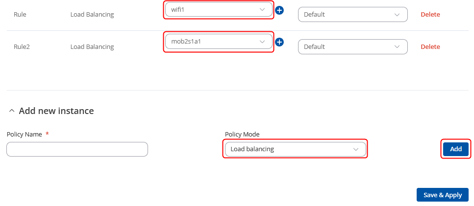
Note - Do not forget to Enable the Load Balancing for mob1s1a1 and Wireless WAN/Wired WAN interfaces.
Overall our rules should look like this:

Testing Configuration
In order to test if the configuration if it's working we will use TCP Dump, TCP Dump will let us capture traffic that goes through each interface of the device.
Installing TCP Dump on RUT
Firstly, you will need to connect to the RUT device's CLI/SSH. You can connect the RUT device CLI via WebUI by navigating to Services → CLI. Log in to CLI with the user name root and the router's admin password.
Now execute these commands one at a time:
opkg update
opkg install tcpdump
To test if TCP Dump has been installed on your device execute the command tcpdump
Testing the configuration via TCPDUMP
The simplest way to test the configuration via tcpdump would be to use two commands from the same device. The first one would be ping to google DNS (from 192.168.1.1 and 192.168.3.1 IPs) and the other would be to tcpdump the correct interface. I will be using the setup of Configurating RUTX12 device for this example, testing devices with one modem is almost identical.
We will do this by opening two instances of your device's CLI/SSH, to access it, login to one of the routers' WebUI and navigate to Services → CLI. Log in to CLI with the user name root and the router's admin password (Open two instances of CLI).
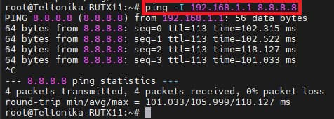
In the first instance, we will let the ping command which will send ICMP requests to 8.8.8.8 from 192.168.1.1(LAN IP). The command for this will be used: ping -I 192.168.1.1 8.8.8.8
On the second instance, we will run TCPDUMP on interface wwan0 to capture if packets are coming through Mobile WAN. The command for this will be used: tcpdump -i wwan0 icmp -n We will also only look at ICMP requests since the Mobile will have a lot of different packets coming in and out.
Output of Ping command
Output of TCPDUMP command
You should see in the tcpdump output that we have ICMP requests going out of the WWAN0 interface, this means that the configuration is working, and 192.168.1.1/24 interface traffic goes through the correct interface, you should also test this on another SIM card(interface).
You can also stop the ping on your device and you should see that ICMP requests stop appearing in the tcpdump output.


