TRB141 1-Wire Setup/Configuration: Difference between revisions
No edit summary |
No edit summary |
||
| (5 intermediate revisions by 3 users not shown) | |||
| Line 5: | Line 5: | ||
Inputs and outputs are used for monitoring and controlling a connected device or receiving signals from that device in order to trigger certain events. | Inputs and outputs are used for monitoring and controlling a connected device or receiving signals from that device in order to trigger certain events. | ||
1-Wire is a voltage-based digital system that works with two contacts, data and ground, for half-duplex bidirectional communication. Compared to other serial communication systems such as I2C or SPI, 1-Wire devices are designed for use in a momentary contact environment. | 1-Wire is a voltage-based digital system that works with two contacts, data and ground, for half-duplex bidirectional communication. Compared to other serial communication systems such as I2C or SPI, 1-Wire devices are designed for use in a momentary contact environment. It is developed by Dallas Semiconductor (now Maxim Integrated) that allows devices to communicate over a single wire using a complex protocol to transfer data. The 1-Wire protocol is commonly used for low-speed communication between microcontrollers and their peripherals, such as temperature sensors, memory devices, and other digital and analog sensors. | ||
Currently, only one Teltonika device (TRB141) supports 1-Wire communication protocol. | |||
In this chapter, we will set up and configure the 1-Wire sensor with '''TRB141'''. | In this chapter, we will set up and configure the 1-Wire sensor with '''TRB141'''. | ||
| Line 17: | Line 19: | ||
==Connecting 1-Wire Sensor with TRB141== | ==Connecting 1-Wire Sensor with TRB141== | ||
First of all we will connect the 1-Wire sensor with TRB141, for this example, | First of all we will connect the 1-Wire sensor with TRB141, for this example, we will be using two different 1-Wire sensors Dallas DS1820 and Dallas DS9092. | ||
Before we proceed with the connection, make sure you know how your 1-Wire sensor has to be connected, or open your 1-Wire sensor data sheet to reference where each wire should be connected. | Before we proceed with the connection, make sure you know how your 1-Wire sensor has to be connected, or open your 1-Wire sensor data sheet to reference where each wire should be connected. | ||
===DS1820 connection=== | ===DS1820 connection=== | ||
---- | |||
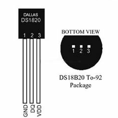
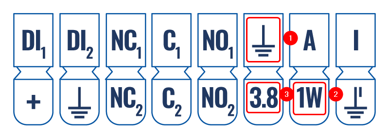
The wiring for DS1820 can be seen in the picture provided below. We will connect the 1st wire to TRB141, the second wire to the 1-Wire pin on TRB141, and the 3rd wire to the + pin. Please see the Wiring of DS1820 and Pinout of TRB141 on which pins should be connected. | The wiring for DS1820 can be seen in the picture provided below. We will connect the 1st wire to TRB141, the second wire to the 1-Wire pin on TRB141, and the 3rd wire to the + pin. Please see the Wiring of DS1820 and Pinout of TRB141 on which pins should be connected. | ||
====Wiring==== | ====Wiring==== | ||
---- | |||
[[File:Networking rut configuration 1 wire wiring v1.png|border|class=tlt-border]] | [[File:Networking rut configuration 1 wire wiring v1.png|border|class=tlt-border]] | ||
====Pinout==== | ====Pinout==== | ||
---- | |||
[[File:Networking trb141 manual input output input output connector pinout | [[File:Networking trb141 manual input output input output connector pinout v7.png|border|class=tlt-border]] | ||
* 1 - Red Wire | * 1 - Red Wire | ||
* 2 - White Wire | * 2 - White Wire | ||
* 3 - Green Wire | * 3 - Green Wire | ||
---- | ---- | ||
===DS9092 connection=== | ===DS9092 connection=== | ||
---- | |||
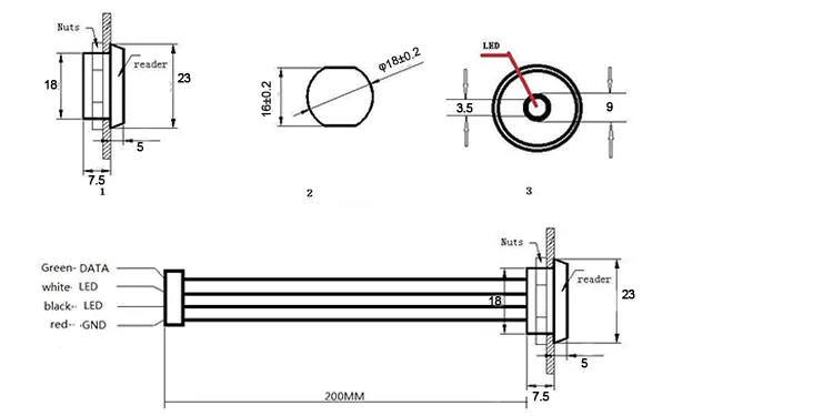
'''Note: Keep in mind that the wire colors of your Ibutton can be different to ones used for this example.''' | '''Note: Keep in mind that the wire colors of your Ibutton can be different to ones used for this example.''' | ||
| Line 51: | Line 47: | ||
====Wiring==== | ====Wiring==== | ||
---- | |||
[[File:Networking rut configuration 1 wire wiring DS9092 v1.png|border|class=tlt-border]] | [[File:Networking rut configuration 1 wire wiring DS9092 v1.png|border|class=tlt-border]] | ||
====Pinout==== | ====Pinout==== | ||
---- | |||
[[File:Networking trb141 manual input output input output connector pinout v4.png|border|class=tlt-border]] | [[File:Networking trb141 manual input output input output connector pinout v4.png|border|class=tlt-border]] | ||
| Line 62: | Line 58: | ||
====Picture-example==== | ====Picture-example==== | ||
---- | |||
[[File:Networking rut configuration 1 wire wiring example v3.jpg|border|class=tlt-border]] | [[File:Networking rut configuration 1 wire wiring example v3.jpg|border|class=tlt-border]] | ||
| Line 75: | Line 73: | ||
===1-Wire activation commands=== | ===1-Wire activation commands=== | ||
---- | |||
In order to read one-wire sensor data you will need to follow these steps: | In order to read one-wire sensor data you will need to follow these steps: | ||
| Line 96: | Line 94: | ||
[[File:Networking trb141 configuration 1 wire cli commands test v1.png|border|class=tlt-border|1100px]] | [[File:Networking trb141 configuration 1 wire cli commands test v1.png|border|class=tlt-border|1100px]] | ||
==Connecting Multiple 1-Wire Sensors with TRB141== | |||
The configuration for connecting multiple 1-wire sensors is the same as above. | |||
There’s no restriction or limit on the number of sensors that can be connected to TRB141. However, there’s a limit on how many sensors can be read every second which is up to 75 sensors only. | |||
===DS18B20 connection=== | |||
---- | |||
The wiring image is a similar scheme that we used as our guide for connecting multiple 1-Wire sensors on the TRB141. | |||
====Wiring==== | |||
---- | |||
[[File:Networking trb1 configuration connectionguide v1.png|border|class=tlt-border|500px]] | |||
====Picture-example==== | |||
---- | |||
[[File:Networking trb1 configuration multi 1wire via breadboard v1.png|border|class=tlt-border|500px]] | |||
==Output== | |||
Enable the 'ioman.gpio.onewire' service. You can configure this by following the instructions above regarding [[TRB141_1-Wire_Setup/Configuration#1-Wire_activation_commands|1-Wire activation commands]]. | |||
We should be able to see all the 1-wire sensor directories and read their values accordingly. | |||
[[File:Networking trb1 configuration cli multi1wire v1.png|border|class=tlt-border|800px]] | |||
[[File:Networking trb1 configuration cli multi1wire output v1.png|border|class=tlt-border|800px]] | |||
28-00000e55f136 = '''31.1 °C''' | |||
28-00000e7dfff9 = '''24.3 °C''' | |||
==Summary== | ==Summary== | ||
| Line 102: | Line 130: | ||
==References== | ==References== | ||
[[TRB141 Input/Output]] | |||
Latest revision as of 14:34, 15 December 2023
The information on this page is updated in accordance with 00.07.04 firmware version.
Introduction
Inputs and outputs are used for monitoring and controlling a connected device or receiving signals from that device in order to trigger certain events.
1-Wire is a voltage-based digital system that works with two contacts, data and ground, for half-duplex bidirectional communication. Compared to other serial communication systems such as I2C or SPI, 1-Wire devices are designed for use in a momentary contact environment. It is developed by Dallas Semiconductor (now Maxim Integrated) that allows devices to communicate over a single wire using a complex protocol to transfer data. The 1-Wire protocol is commonly used for low-speed communication between microcontrollers and their peripherals, such as temperature sensors, memory devices, and other digital and analog sensors.
Currently, only one Teltonika device (TRB141) supports 1-Wire communication protocol.
In this chapter, we will set up and configure the 1-Wire sensor with TRB141.
Prerequisites
- TRB141
- 1-Wire sensor
- If 1-Wire doesn't have its Wires(Like Dallas DS1820 used in this example) you will need additional wires to connect the sensor to TRB141
Connecting 1-Wire Sensor with TRB141
First of all we will connect the 1-Wire sensor with TRB141, for this example, we will be using two different 1-Wire sensors Dallas DS1820 and Dallas DS9092. Before we proceed with the connection, make sure you know how your 1-Wire sensor has to be connected, or open your 1-Wire sensor data sheet to reference where each wire should be connected.
DS1820 connection
The wiring for DS1820 can be seen in the picture provided below. We will connect the 1st wire to TRB141, the second wire to the 1-Wire pin on TRB141, and the 3rd wire to the + pin. Please see the Wiring of DS1820 and Pinout of TRB141 on which pins should be connected.
Wiring
Pinout
- 1 - Red Wire
- 2 - White Wire
- 3 - Green Wire
DS9092 connection
Note: Keep in mind that the wire colors of your Ibutton can be different to ones used for this example.
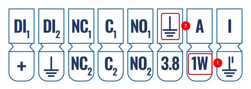
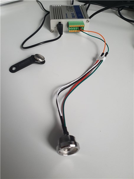
The wiring for DS9092 can be seen in the picture provided below. We will connect the Green Wire to TRB141 1-Wire Pin, the Red Wire to the Ground pin on TRB141. Please see the Wiring of DS9092 and Pinout of TRB141 on which pins should be connected.
Wiring
Pinout
- 1 - Green Wire
- 2 - Red Wire
Picture-example
1-Wire configuration on TRB141
1-Wire configuration is simple, you will only need to log in to your device's CLI/SSH and execute a few commands.
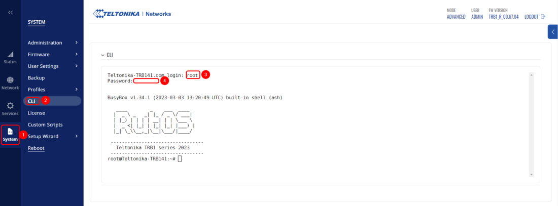
Firstly, let's connect to your device's CLI. Open your WebUI by opening Browser on your computer and inputting your device's IP(by default 192.168.2.1). Now navigate to System → CLI. Login with your root username and your admin password:
1-Wire activation commands
In order to read one-wire sensor data you will need to follow these steps:
- Set one-wire sensor value to "1' using the ubus command:
ubus call ioman.gpio.onewire update '{"value":"1"}' - List the connected one-wire devices from the /sys/bus/w1/devices directory using the ls command:
ls /sys/bus/w1/devices
- Choose a sensor to read and obtain its state from the /sys/bus/w1/devices/<device_name>/w1_slave directory:
cat /sys/bus/w1/devices/<device_name>/w1_slave
Commands executed on CLI:
Testing the configuration
The configuration testing is straight forward, you will need to execute command cat /sys/bus/w1/devices/<device_name>/w1_slave you should see the data from your sensor in the CLI output, keep in mind that the output entirely depends on the 1-Wire sensor used, so most likely you will see different outup. And if you will be using a similar 1-Wire device to DS9092 you will need to touch and hold the key for a few seconds until you would see the slave device.
Connecting Multiple 1-Wire Sensors with TRB141
The configuration for connecting multiple 1-wire sensors is the same as above. There’s no restriction or limit on the number of sensors that can be connected to TRB141. However, there’s a limit on how many sensors can be read every second which is up to 75 sensors only.
DS18B20 connection
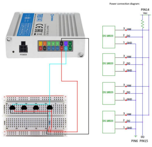
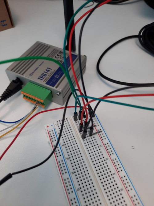
The wiring image is a similar scheme that we used as our guide for connecting multiple 1-Wire sensors on the TRB141.
Wiring
Picture-example
Output
Enable the 'ioman.gpio.onewire' service. You can configure this by following the instructions above regarding 1-Wire activation commands.
We should be able to see all the 1-wire sensor directories and read their values accordingly.
28-00000e55f136 = 31.1 °C
28-00000e7dfff9 = 24.3 °C
Summary
In this article we connected and configurated different 1-Wire sensors and learned how to configure the 1-Wire sensor to display data on TRB141 SSH/CLI. Additionally, in this article you can find how different 1-Wire sensors have to be wired/connected to TRB141.

