Wireless distribution system (WDS): Difference between revisions
No edit summary |
m (Domnev moved page Wireless distribution system (WDS) test to Wireless distribution system (WDS)) |
||
| (9 intermediate revisions by 2 users not shown) | |||
| Line 1: | Line 1: | ||
<p style="color:red">The information in this page is updated in accordance with [https://wiki.teltonika-networks.com/view/FW_%26_SDK_Downloads'''00.07. | <p style="color:red">The information in this page is updated in accordance with [https://wiki.teltonika-networks.com/view/FW_%26_SDK_Downloads'''00.07.09.1'''] firmware version.</p> | ||
==Introduction== | ==Introduction== | ||
Introduction | |||
Wireless | '''Introduction''' | ||
This article provides | |||
If you | The Wireless Distribution System (WDS) enables access points to connect wirelessly within an IEEE 802.11 network, acting as a Layer 2 bridge, allowing the expansion of the wireless network through multiple access points without requiring a wired backbone. A key advantage of WDS is that it preserves the MAC addresses of client frames when transmitting between access points. | ||
This article provides a detailed configuration example for setting up a basic WDS with two RUTxxx devices. | |||
If you cannot locate some of the parameters described here in your device’s WebUI, make sure to enable '''Advanced WebUI Mode''' by clicking the “Advanced” button at the top of the WebUI. | |||
[[File:Networking_rutos_manual_webui_basic_advanced_mode_75.gif|border|center|class=tlt-border|1102x93px]] | [[File:Networking_rutos_manual_webui_basic_advanced_mode_75.gif|border|center|class=tlt-border|1102x93px]] | ||
---- | ---- | ||
| Line 21: | Line 25: | ||
[[File:WDS configuration topology.png|border|center|class=tlt-border|935x443px]] | [[File:WDS configuration topology.png|border|center|class=tlt-border|935x443px]] | ||
The | The diagram above depicts two RUTxxx routers: RUT1 and RUT2. | ||
* RUT1 is set to '''Access Point''' Mode with SSID: RUT_WiFi. | |||
* RUT2 is configured as a Client (AP) mode and connects to Wi-Fi with SSID: RUT_WiFi. RUT2’s DHCP server is disabled to allow devices connected to RUT2 to receive IP addresses from RUT1’s DHCP server via WDS. | |||
This configuration effectively merges both routers into a single network, allowing seamless communication between devices. | |||
''' | '''Note''': Parameters like LAN IP addresses and Wi-Fi SSIDs should be customized to meet your specific needs. | ||
==Router configuration== | ==Router configuration== | ||
Once you've reviewed the configuration scheme and ensured all devices are prepared, you can begin configuring your routers by following the instructions below. | |||
===RUT1=== | ===RUT1 Configuration=== | ||
---- | ---- | ||
The configuration | The RUT1 configuration is straightforward. Ensure the router has: | ||
* An active WiFi Access Point (AP) | * An active WiFi Access Point (AP) with WDS enabled | ||
* An active DHCP Server | * An active DHCP Server | ||
To change the LAN IP address, log into the router's WebUI and navigate to '''Network → LAN → LAN Settings''', then click the '''Edit''' button next to the LAN settings. | |||
[[File:WDS configuration lan edit.png|border|1100x1100px]] | [[File:WDS configuration lan edit.png|border|1100x1100px]] | ||
By default, RUTxxx routers have a Wi-Fi AP and DHCP server enabled. If you need to modify these settings, go to '''Network → DHCP → Server Settings''' and click '''Edit'''. | |||
[[File:WDS configuration dhcp edit.png|border|1100x1100px]] | [[File:WDS configuration dhcp edit.png|border|1100x1100px]] | ||
To configure the Wi-Fi AP, go to '''Network → Wireless → SSIDs''', then click the '''Edit''' button for the desired wireless network. | |||
[[File:RutOS Relay WIFI extender 7.8 wifi edit.png|border|1100x1100px]] | [[File:RutOS Relay WIFI extender 7.8 wifi edit.png|border|1100x1100px]] | ||
Next, go to the '''Advanced Settings''' tab and enable '''WDS'''. | |||
[[File:WDS configuration enable wds_1.png|border|1100x1100px]] | [[File:WDS configuration enable wds_1.png|border|1100x1100px]] | ||
===RUT2=== | |||
===RUT2 Configuration=== | |||
---- | ---- | ||
''' | For RUT2, the key steps are: | ||
* Scan and connect to RUT1’s Wi-Fi Access Point | |||
* Change the network from ''auto (wifi0)'' to ''lan'' | |||
* Enable WDS in the '''Advanced Settings''' | |||
* Change the default IPv4 address to ''192.168.10.2'' and disable the DHCP server | |||
==== | '''NOTE''': Follow these steps in the given order. Disabling RUT2's DHCP server first might cause loss of access to the router. Start by configuring Wi-Fi. | ||
====Wi-Fi Configuration==== | |||
---- | ---- | ||
- | * To configure Wi-Fi, log into RUT2’s WebUI and navigate to '''Network → Wireless → SSIDs'''. | ||
* | |||
* Click '''Scan''' to search for nearby Wi-Fi networks and connect to RUT1’s Access Point. You can choose to scan either the 2.4 GHz or 5 GHz band. | |||
[[File:RutOS Relay WIFI extender 7.8 wifi scan.png|border|1100x1100px]] | [[File:RutOS Relay WIFI extender 7.8 wifi scan.png|border|1100x1100px]] | ||
* | |||
* After the scan, select RUT1’s Access Point and click '''Join network'''. | |||
[[File:RutOS Relay WIFI extender 7.8 wifi scan connect.png|border|1100x1100px]] | [[File:RutOS Relay WIFI extender 7.8 wifi scan connect.png|border|1100x1100px]] | ||
* | |||
* Enter the Wi-Fi password or WPA passphrase for RUT1's Access Point. | |||
[[File:RutOS Relay WIFI extender 7.8 wifi scan connect join.png|border|1100x1100px]] | [[File:RutOS Relay WIFI extender 7.8 wifi scan connect join.png|border|1100x1100px]] | ||
* | |||
* In the Wireless Client Configuration window, change the '''Network setting''' to ''lan''. | |||
[[File:WDS configuration wifi client interface.png|border|1100x1100px]] | [[File:WDS configuration wifi client interface.png|border|1100x1100px]] | ||
* In the '''Advanced Settings''' tab, enable '''WDS'''. | |||
[[File:WDS configuration enable wds_1.png|border|1100x1100px]] | [[File:WDS configuration enable wds_1.png|border|1100x1100px]] | ||
* | |||
====LAN and DHCP Configuration==== | |||
---- | |||
* Once the Wi-Fi is configured, update the LAN settings. Go to '''Network → LAN''', then click '''Edit'''. | |||
[[File:WDS configuration lan client edit_1.png|border|1100x1100px]] | [[File:WDS configuration lan client edit_1.png|border|1100x1100px]] | ||
* After you clicked Edit button settings window will appear. Change IPv4 address and IPv4 netmask, disable DHCPv4 and DHCPv6 settings. | * After you clicked Edit button settings window will appear. Change IPv4 address and IPv4 netmask, disable DHCPv4 and DHCPv6 settings. | ||
| Line 100: | Line 134: | ||
[[File:WDS configuration lan client edit.png|border|1100x1100px]] | [[File:WDS configuration lan client edit.png|border|1100x1100px]] | ||
==Testing the Setup== | |||
Once the configuration is complete, it's essential to test it to ensure everything works as expected. | |||
To test, log into either router and navigate to '''System → Maintenance → CLI'''. Log in with the username: ''root'' and the router’s admin password. Ping the other router or any connected device by typing ''ping <device_ip>'' in the console and pressing Enter: | |||
[[File:WDS configuration pinging example.png]] | [[File:WDS configuration pinging example.png]] | ||
Replace <devices_ip> with an actual IP address of a device that is in your network and if the ping requests are successful it means the configuration is working. You can check the IP addresses of the devices connected to your network in RUT1's Status → Routes section. | |||
Replace ''<devices_ip>'' with an actual IP address of a device that is in your network and if the ping requests are successful it means the configuration is working. You can check the IP addresses of the devices connected to your network in RUT1's Status → Routes section. | |||
Latest revision as of 08:36, 21 October 2024
The information in this page is updated in accordance with 00.07.09.1 firmware version.
Introduction
Introduction
The Wireless Distribution System (WDS) enables access points to connect wirelessly within an IEEE 802.11 network, acting as a Layer 2 bridge, allowing the expansion of the wireless network through multiple access points without requiring a wired backbone. A key advantage of WDS is that it preserves the MAC addresses of client frames when transmitting between access points.
This article provides a detailed configuration example for setting up a basic WDS with two RUTxxx devices.
If you cannot locate some of the parameters described here in your device’s WebUI, make sure to enable Advanced WebUI Mode by clicking the “Advanced” button at the top of the WebUI.

Configuration overview and prerequisites
Before we begin, let's overview the configuration that we are attempting to achieve and the prerequisites that make it possible.
Prerequisites:
- Two RUTxxx routers
- Router's LANs should be in same subnet
- An end device (PC, Laptop, Tablet, Smartphone)
Configuration scheme:
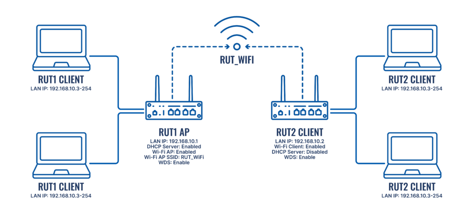
The diagram above depicts two RUTxxx routers: RUT1 and RUT2.
- RUT1 is set to Access Point Mode with SSID: RUT_WiFi.
- RUT2 is configured as a Client (AP) mode and connects to Wi-Fi with SSID: RUT_WiFi. RUT2’s DHCP server is disabled to allow devices connected to RUT2 to receive IP addresses from RUT1’s DHCP server via WDS.
This configuration effectively merges both routers into a single network, allowing seamless communication between devices.
Note: Parameters like LAN IP addresses and Wi-Fi SSIDs should be customized to meet your specific needs.
Router configuration
Once you've reviewed the configuration scheme and ensured all devices are prepared, you can begin configuring your routers by following the instructions below.
RUT1 Configuration
The RUT1 configuration is straightforward. Ensure the router has:
- An active WiFi Access Point (AP) with WDS enabled
- An active DHCP Server
To change the LAN IP address, log into the router's WebUI and navigate to Network → LAN → LAN Settings, then click the Edit button next to the LAN settings.
By default, RUTxxx routers have a Wi-Fi AP and DHCP server enabled. If you need to modify these settings, go to Network → DHCP → Server Settings and click Edit.
To configure the Wi-Fi AP, go to Network → Wireless → SSIDs, then click the Edit button for the desired wireless network.
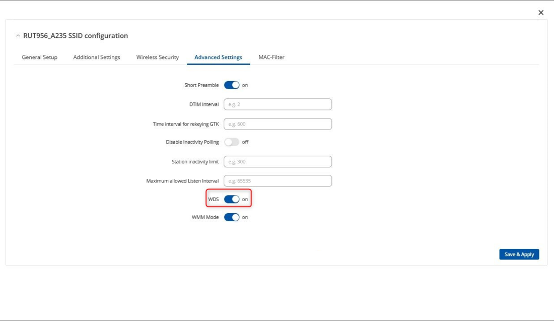
Next, go to the Advanced Settings tab and enable WDS.
RUT2 Configuration
For RUT2, the key steps are:
- Scan and connect to RUT1’s Wi-Fi Access Point
- Change the network from auto (wifi0) to lan
- Enable WDS in the Advanced Settings
- Change the default IPv4 address to 192.168.10.2 and disable the DHCP server
NOTE: Follow these steps in the given order. Disabling RUT2's DHCP server first might cause loss of access to the router. Start by configuring Wi-Fi.
Wi-Fi Configuration
- To configure Wi-Fi, log into RUT2’s WebUI and navigate to Network → Wireless → SSIDs.
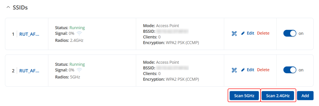
- Click Scan to search for nearby Wi-Fi networks and connect to RUT1’s Access Point. You can choose to scan either the 2.4 GHz or 5 GHz band.
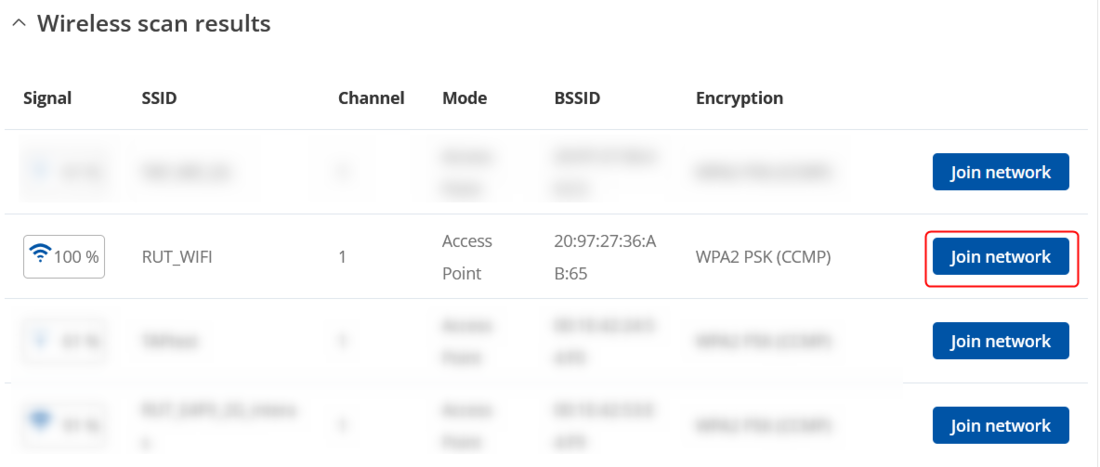
- After the scan, select RUT1’s Access Point and click Join network.
- Enter the Wi-Fi password or WPA passphrase for RUT1's Access Point.
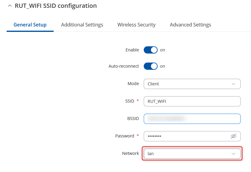
- In the Wireless Client Configuration window, change the Network setting to lan.
- In the Advanced Settings tab, enable WDS.
LAN and DHCP Configuration
- Once the Wi-Fi is configured, update the LAN settings. Go to Network → LAN, then click Edit.
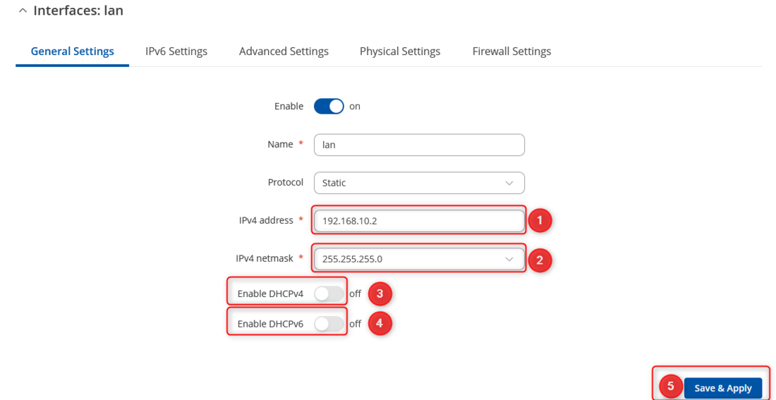
- After you clicked Edit button settings window will appear. Change IPv4 address and IPv4 netmask, disable DHCPv4 and DHCPv6 settings.
- Change IPv4 address
- Change IPv4 netmask
- Disable DHCPv4
- Disable DHCPv6
- Save
Testing the Setup
Once the configuration is complete, it's essential to test it to ensure everything works as expected.
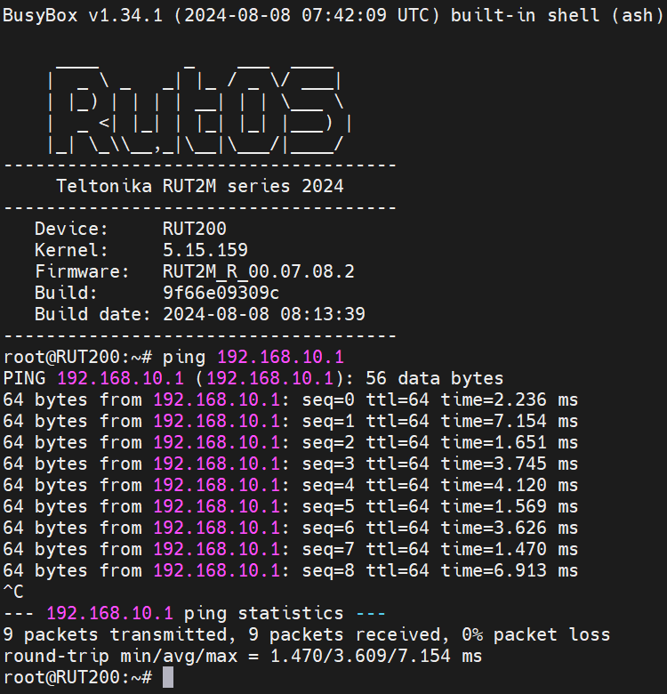
To test, log into either router and navigate to System → Maintenance → CLI. Log in with the username: root and the router’s admin password. Ping the other router or any connected device by typing ping <device_ip> in the console and pressing Enter:
Replace <devices_ip> with an actual IP address of a device that is in your network and if the ping requests are successful it means the configuration is working. You can check the IP addresses of the devices connected to your network in RUT1's Status → Routes section.


