Separating Mobile Data Traffic: Using First SIM Card For LAN Traffic and Second SIM Card For WLAN Traffic: Difference between revisions
No edit summary |
No edit summary |
||
| (3 intermediate revisions by 2 users not shown) | |||
| Line 1: | Line 1: | ||
<p style="color:red">The information in this page is updated in accordance with firmware version '''[https://wiki.teltonika-networks.com/view/FW_%26_SDK_Downloads 00.07.10]''' | |||
==Introduction== | ==Introduction== | ||
This article provides a guide on how to separate mobile data traffic by using first SIM card for LAN traffic and second SIM card for WLAN traffic. These configurations are specifically made for RUTX12. | This article provides a guide on how to separate mobile data traffic by using first SIM card for LAN traffic and second SIM card for WLAN traffic. These configurations are specifically made for RUTX12. | ||
---- | |||
If you're having trouble finding any page or some of the parameters described here on your device's WebUI, you should turn on '''"Advanced WebUI"''' mode. You can do that by clicking the '''"Advanced"''' button which is located at the top-right corner of the WebUI. | |||
[[File:Networking | [[File:Networking rutos manual webui basic advanced mode 75.gif|border|class=tlt-border|1004x1004px]] | ||
---- | ---- | ||
==Creating A LAN Interface For WLAN== | |||
* Go to '''Network''' → '''Wireless''' → '''SSIDs''' | |||
* Press the '''Edit''' button next to the WLAN whose traffic you want to route through a different SIM card. | |||
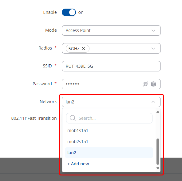
* In the opened tab, next to '''Network''' from the dropdown meniu press '''Add new''' and enter the desired LAN name. | |||
[[File: | [[File:AddNewInterfaceV1.png|border|class=tlt-border|]] | ||
* | * In the newly opened tab: | ||
# Write the '''desired IPv4 address'''. | |||
# Enable '''DHCP'''. | |||
# Press '''Save & Apply'''. | |||
[[File: | [[File:LanConfigForWLANV1.png|border|class=tlt-border|]] | ||
==Configuring Policy Based Routing== | |||
* Go to '''Network''' → '''Routing''' → '''Policy Based Routing''' | |||
* Go to '''Network''' → '''Routing''' → ''' | |||
* Under the "Add New Instance" tab, enter the ID and name for your new Routing Table, for our use, we will need 2 Routing Tables | * Under the "Add New Instance" tab, enter the ID and name for your new Routing Table, for our use, we will need 2 Routing Tables | ||
* Create a routing table with these parameters: '''ID''': 100, '''Name''': first | * Create a routing table with these parameters: '''ID''': 100, '''Name''': first | ||
* Click '''Add''' | |||
[[File:FirstRoutingTableV1.png|border|1100px|class=tlt-border|]] | |||
[[File: | ---- | ||
* In the configuration window, under the '''Static IPV4 Routes''' tab, click '''Add''' | * In the configuration window, under the '''Static IPV4 Routes''' tab, click '''Add''' | ||
* Enter these parameters: '''Interface''': mob1s1a1, '''Target''': 0.0.0.0, '''Netmask''': 0.0.0.0 | * Enter these parameters: '''Interface''': mob1s1a1, '''Target''': 0.0.0.0, '''Netmask''': 0.0.0.0 | ||
* Leave the rest of the parameters on their default values and click '''Save & Apply''' | |||
[[File:FirstRoutingTableP2V1.png|border|1100px|class=tlt-border|]] | |||
---- | |||
* Create a second routing table with these parameters: '''ID''': 200, '''Name''': second | * Create a second routing table with these parameters: '''ID''': 200, '''Name''': second | ||
* Click '''Add''' | |||
[[File:SecondRoutingTableV1.png|border|1100px|class=tlt-border|]] | |||
[[File: | ---- | ||
* In the configuration window, under the '''Static IPV4 Routes''' tab, click '''Add''' | * In the configuration window, under the '''Static IPV4 Routes''' tab, click '''Add''' | ||
* Enter these parameters: '''Interface''': mob2s1a1, '''Target''': 0.0.0.0, '''Netmask''': 0.0.0.0 | * Enter these parameters: '''Interface''': mob2s1a1, '''Target''': 0.0.0.0, '''Netmask''': 0.0.0.0 | ||
* Leave the rest of the parameters on their default values and click '''Save & Apply''' | * Leave the rest of the parameters on their default values and click '''Save & Apply''' | ||
[[File:SecondRoutingTableP2V1.png|border|1100px|class=tlt-border|]] | |||
[[File: | |||
---- | |||
* Go to '''Network''' → '''Routing''' → '''Policy Based Routing''' → '''Routing Rules For IPV4''' and press '''ADD''' button. | |||
* Create 2 new rules with these parameters: | * Create 2 new rules with these parameters: | ||
First Rule: '''Priority:''' 1 | *First Rule: | ||
#'''Priority:''' 1 | |||
#'''Incoming interface:''' lan | |||
#'''Lookup table:''' 100 | |||
[[File: | [[File:FirstRoutingRulesV1.png|border|class=tlt-border|]] | ||
---- | |||
*Second Rule: | |||
#'''Priority:''' 1 | |||
#'''Incoming interface:''' lan2 | |||
#'''Lookup table:''' 200 | |||
[[File:SecondRoutingRulesV1.png|border|class=tlt-border|]] | |||
==Separating Traffic Via Ethernet Ports== | |||
* Go to '''Network''' → '''VLAN''' | This example could also be applied when there is a need to split ethernet ports traffic via different SIM cards. | ||
---- | |||
===Configuring VLANs=== | |||
To start with we will need to create new VLAN. | |||
* Go to '''Network''' → '''VLAN'''→ '''Port Based''' and press '''ADD''' button. | |||
* Once new VLAN appears, '''untag''' desired ports from '''VLAN 1''' and '''tag''' them on '''VLAN 3'''. In this example ports 3 and 4 will be used in VLAN 3. | |||
* | |||
[[File:VLANForTrafficSplitV1.png|border|1100px|class=tlt-border|]] | |||
---- | |||
===Configuring LAN=== | |||
*Navigate to '''Network'''→'''LAN''' and press '''Edit''' button next to the previously created LAN. | |||
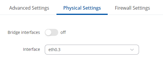
* In '''Physical Settings''' select new VLAN. In this example '''eth0.3''' after that press '''Save & Apply'''. | |||
[[File: | [[File:LanSettingsForVLANV1.png|border|class=tlt-border|]] | ||
* | ===Testing the configuration=== | ||
To test the configuration simply connect to one of the ports that are in LAN and check the IP address, then connect to the port that is in different LAN and check again the IP address. For this test icanhazip.com website will be used. | |||
* End device connected to first LAN: | |||
[[File:TrafficSplitLANTestV1.png|border|class=tlt-border|]] | |||
* End device connected to second LAN: | |||
[[File:TrafficSplitNewLANTestV1.png|border|class=tlt-border|]] | |||
[[Category: Router control and monitoring]] | |||
Latest revision as of 08:46, 15 October 2024
Main Page > General Information > Configuration Examples > Router control and monitoring > Separating Mobile Data Traffic: Using First SIM Card For LAN Traffic and Second SIM Card For WLAN TrafficThe information in this page is updated in accordance with firmware version 00.07.10
Introduction
This article provides a guide on how to separate mobile data traffic by using first SIM card for LAN traffic and second SIM card for WLAN traffic. These configurations are specifically made for RUTX12.
If you're having trouble finding any page or some of the parameters described here on your device's WebUI, you should turn on "Advanced WebUI" mode. You can do that by clicking the "Advanced" button which is located at the top-right corner of the WebUI.

Creating A LAN Interface For WLAN
- Go to Network → Wireless → SSIDs
- Press the Edit button next to the WLAN whose traffic you want to route through a different SIM card.
- In the opened tab, next to Network from the dropdown meniu press Add new and enter the desired LAN name.
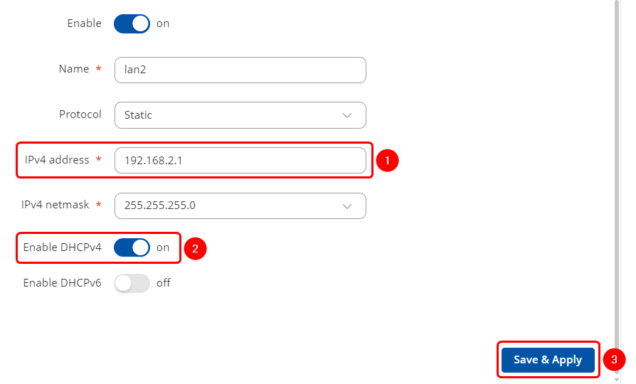
- In the newly opened tab:
- Write the desired IPv4 address.
- Enable DHCP.
- Press Save & Apply.
Configuring Policy Based Routing
- Go to Network → Routing → Policy Based Routing
- Under the "Add New Instance" tab, enter the ID and name for your new Routing Table, for our use, we will need 2 Routing Tables
- Create a routing table with these parameters: ID: 100, Name: first
- Click Add
- In the configuration window, under the Static IPV4 Routes tab, click Add
- Enter these parameters: Interface: mob1s1a1, Target: 0.0.0.0, Netmask: 0.0.0.0
- Leave the rest of the parameters on their default values and click Save & Apply
- Create a second routing table with these parameters: ID: 200, Name: second
- Click Add
- In the configuration window, under the Static IPV4 Routes tab, click Add
- Enter these parameters: Interface: mob2s1a1, Target: 0.0.0.0, Netmask: 0.0.0.0
- Leave the rest of the parameters on their default values and click Save & Apply
- Go to Network → Routing → Policy Based Routing → Routing Rules For IPV4 and press ADD button.
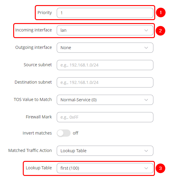
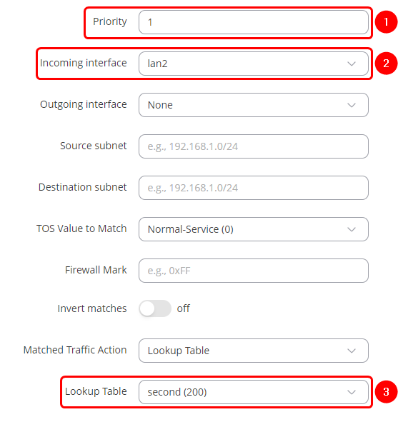
- Create 2 new rules with these parameters:
- First Rule:
- Priority: 1
- Incoming interface: lan
- Lookup table: 100
- Second Rule:
- Priority: 1
- Incoming interface: lan2
- Lookup table: 200
Separating Traffic Via Ethernet Ports
This example could also be applied when there is a need to split ethernet ports traffic via different SIM cards.
Configuring VLANs
To start with we will need to create new VLAN.
- Go to Network → VLAN→ Port Based and press ADD button.
- Once new VLAN appears, untag desired ports from VLAN 1 and tag them on VLAN 3. In this example ports 3 and 4 will be used in VLAN 3.
Configuring LAN
- Navigate to Network→LAN and press Edit button next to the previously created LAN.
- In Physical Settings select new VLAN. In this example eth0.3 after that press Save & Apply.
Testing the configuration
To test the configuration simply connect to one of the ports that are in LAN and check the IP address, then connect to the port that is in different LAN and check again the IP address. For this test icanhazip.com website will be used.
- End device connected to first LAN:
- End device connected to second LAN:

