RUT950 Network: Difference between revisions
No edit summary |
mNo edit summary |
||
| Line 2: | Line 2: | ||
| name = RUT950 | | name = RUT950 | ||
| series = RUT9xx | | series = RUT9xx | ||
| fw_version = RUT9XX_R_00.06.05.1 | |||
| mobile = 4g | | mobile = 4g | ||
| file_mobile = Networking_rut9xx_manual_network_mobile_information_4g_v2.png | | file_mobile = Networking_rut9xx_manual_network_mobile_information_4g_v2.png | ||
Revision as of 10:10, 19 November 2019
Main Page > EOL Products > RUT950 > RUT950 Manual > RUT950 WebUI > RUT950 Status section > RUT950 NetworkSummary
The Network page contains information related to the device's networking features. This chapter is an overview of the Network page in RUT950 devices.
Mobile
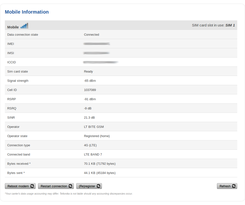
The Mobile section displays information about the mobile connection and the SIM card in use. The figure below is an example of the Mobile page:
| field name | description |
|---|---|
| Data connection state | Indicates whether the device has an active mobile data connection |
| IMEI | The IMEI (International Mobile Equipment Identity) is a unique 15 decimal digit number used to identify cellular modules. GSM network operators use the IMEI to identify devices in their networks |
| IMSI | The IMSI (international mobile subscriber identity) is a unique 15 decimal digit (or less) number used to identify the user of a cellular network |
| ICCID | SIM card's ICCID is a unique serial number used to identify the SIM chip |
| SIM card state | The current SIM card state. Possible values are:
|
| Signal strength | Received signal strength indicator (RSSI) measured in dBm. Values closer to 0 indicate a better signal strength |
| Cell ID | The ID of the cell that the modem is currently connected to |
| Signal level measurements | Overall signal quality is defined by different measurements for different connection types. Short explanations and recommendations are provided below. Click here for more in-depth information or click on one of the links below:
|
| Operator | Network operator's name |
| Operator state | Shows whether the network has currently indicated the registration of the mobile device. Possible values are:
|
| Connection type | Mobile connection connection type. Possible values are:
|
| Connected band | Currently used frequency band. For more information on supported frequency bands, click here |
| Bytes received | Amount of data received through the mobile interface |
| Bytes sent | Amount of data sent through the mobile interface |
| Restart Modem | Reboots the device's cellular module |
| Restart Connection | Restarts the mobile connection |
| (Re)register | Registers to the mobile network |
| Refresh | Refreshes all information fields in the page |
WAN
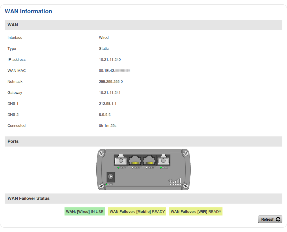
The WAN section displays information about the Main and Backup WAN connections. The figure below is an example of the Mobile page:
| Field | Description |
|---|---|
| Interface | WAN type. Possible values are:
|
| Type | Connection type or protocol. The value displayed in this field is dependent on used WAN type. Possible values are:
|
| IP address | Router's WAN IP address |
| WAN MAC | MAC address of the WAN network interface controller (WiFi radio or WAN Ethernet port). This field is only visible if main WAN is set to Wired or WiFi |
| Netmask | A netmask is used to define how "large" a network is by specifying which part of the IP address denotes the network and which part denotes the device |
| Gateway | Gateway of the default route - an IP address through which the router reaches the Internet |
| DNS | DNS servers used by the main WAN connection |
| Connected | Currently used WAN connection uptime |
| Ports | Displays an image of the router's back panel with highlighted Ethernet ports that are currently in use |
| WAN Failover Status | Displays the router's current WAN failover status |
| Refresh | Refreshes all information fields in the page |
WAN settings can be customized via the Network → WAN page.
LAN
The LAN section displays information about your Local Area Network and active DHCP leases.
LAN Information
The LAN Information section contains data on the router's LAN interface(s). The figure below is an example of the LAN Information section:
| Field | Description |
|---|---|
| Name | LAN interface name |
| IP address | Router's LAN IP address |
| Netmask | A netmask is used to define how "large" a network is by specifying which part of the IP address denotes the network and which part denotes the device |
| Ethernet MAC address | Router's LAN MAC address |
| Connected for | LAN interface uptime |
DHCP Leases
The DHCP Leases section contains information on DHCP clients that hold active DHCP lease. The figure below is an example of the DHCP Leases section:
| Field | Description |
|---|---|
| Hostname | DHCP client's hostname. |
| IP address | DHCP client's IP address. |
| LAN name | LAN interface name through which the client is connected to the router. |
| MAC address | DHCP client's MAC address. |
| Lease time remaining | Remaining lease time for a DHCP client. Active DHCP lease holders will try to renew their DHCP leases after a half of the lease time passes. DHCP lease settings can be changed in the Network → LAN → DHCP Server section. |
Ports
The Ports displays an image of the router's front panel with highlighted Ethernet ports that are currently in use. The Refresh button refreshes all information fields in the page. The figure below is an example of the Ports section:
Wireless
The Wireless section displays information about wireless connections and associated WiFi stations.
Wireless Information
The figure below is an example of the Wireless Information section:
| Field name | Description |
|---|---|
| Channel | Currently used channel. In most countries there are 13 WiFi channels on the 2.4 GHz band (14 in Japan) to choose from |
| Country Code | Indicates currently used country code (SO/IEC 3166 alpha2 country codes as defined in ISO 3166-1 standard) |
Wireless Status
The Wireless Status section contains information about Wireless Access Points. The figure below is an example of the Wireless Status section:
| Field name | Description |
|---|---|
| SSID | The broadcasted SSID (Service Set Identifier) of the wireless network |
| Mode | Connection mode. Can either be Access Point (AP) or Client. In AP mode others can connect to this router's wireless connection. In client mode router connects to other wireless networks |
| Encryption | The type of WiFi encryption used |
| Wireless MAC | The MAC (Media Access Control) address of the access point radio |
| Signal Quality | The signal quality between router's radio and some other device that is connected to the router |
| Bit rate | The maximum possible physical throughput that the router's radio can handle. Bit rate will be shared between router and other possible devices which connect to local Access Point (AP) |
Associated Stations
The Associated Stations section contains information about devices that are connected to Wireless Access Point. The figure below is an example of the Associated Stations section:
| Field name | Description |
|---|---|
| MAC address | Associated station's MAC (Media Access Control) address |
| Device Name | Currently connected device name |
| Signal | Received Signal Strength Indicator (RSSI). Signal's strength measured in dBm |
| RX rate | The rate at which packets are received from associated station |
| TX rate | The rate at which packets are sent to associated station |


