RUT240 Monitoring via Modbus: Difference between revisions
No edit summary |
No edit summary |
||
| Line 1: | Line 1: | ||
{{Template: | {{Template: Networking_rut_configuration_examples_monitoring_via_modbus | ||
|name = RUT240 | <!------------------------DEVICE-----------------------> | ||
|series = RUT2XX | | name = RUT240 | ||
| series = RUT2XX | |||
}} | }} | ||
Revision as of 11:07, 20 November 2020
Main Page > EOL Products > RUT240 > RUT240 Configuration Examples > RUT240 Monitoring via ModbusRouter monitoring via Modbus TCP Linux guide applies to RUT240 routers.

Introduction
Modbus is a serial communications protocol originally published by Modicon (now Schneider Electric) in 1979 for use with its programmable logic controllers (PLCs). Modbus has become a de facto standard communication protocol and is now a commonly available means of connecting industrial electronic devices. The main reasons for the use of Modbus in the industrial environment are:
- developed with industrial applications in mind,
- openly published and royalty-free,
- easy to deploy and maintain,
- moves raw bits or words without placing many restrictions on vendors.
Modbus enables communication among many devices connected to the same network, for example, a system that measures temperature and humidity and communicates the results to a computer. Modbus is often used to connect a supervisory computer with a remote terminal unit (RTU) in supervisory control and data acquisition (SCADA) systems. Many of the data types are named from its use in driving relays: a single-bit physical output is called a coil, and a single-bit physical input is called a discrete input or a contact.
This article provides a guide on how to use Modbus TCP to monitor RUT240 routers with a PC using a Linux Operating System.
Configuring the router
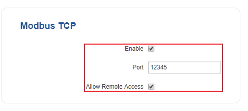
In order to start using Modbus TCP, we must first configure the router. Modbus TCP configuration from the router's side is very simple. All you need to do is log in to the router's WebUI, go to Services → Modbus, Enable the Modbus TCP service, enter a Port number through which the Modbus TCP communication will take place and Allow remote access if you wish to connect to the router remotely (from WAN).
Installing the necessary software
Next you'll need software capable of communicating via Modbus. The software that we'll be using for this guide is called modbus-cli. To get it you'll first have to install ruby. To do so, open the Terminal app and enter these commands.
$ sudo apt-get install ruby
$ sudo gem install modbus-cli
Getting router parameters
Modbus TCP can be used to both get and set certain router parameters. First lets do an overview of how to obtain parameters via Modbus TCP. Please keep in mind that in order to get routers parameters when using Request Configuration you need to use Register Number instead of Register Address.
List of parameters
Router parameters are held within registers. Each register contains 2 bytes of information. For simplification the number of registers for storing numerical values is 2, while the number of registers for storing text information is 16. The register addresses and corresponding system values are described in the table below:
Get Parameters
Modbus parameters are held within registers. Each register contains 2 bytes of information. For simplification, the number of registers for storing numbers is 2 (4 bytes), while the number of registers for storing text information is 16 (32 bytes).
The register numbers and corresponding system values are described in the table below:
| required value | register address | register number | number of registers | representation |
|---|---|---|---|---|
| System uptime | 1 | 2 | 2 | 32 bit unsigned integer |
| System hostname | 7 | 8 | 16 | Text |
| Router serial number | 39 | 40 | 16 | Text |
| LAN MAC address | 55 | 56 | 16 | Text |
| Router name | 71 | 72 | 16 | Text |
| Current WAN IP address | 139 | 140 | 2 | 8 bit unsigned integer |
| Digital non-isolated input | 324 | 325 | 1 | 16 bit unsigned integer |
| Digital open collector output | 325 | 326 | 1 | 16 bit unsigned integer |
| PIN 3 direction | 326 | 327 | 1 | 16 bit unsigned integer |
| PIN 4 direction | 327 | 328 | 1 | 16 bit unsigned integer |
| Unix timestamp | 364 | 365 | 2 | 32 bit unsigned integer |
| Local ISO time | 366 | 367 | 12 | Text |
| UTC time | 378 | 379 | 12 | Text |
| LAN IP | 394 | 395 | 2 | 8 bit unsigned integer |
Modbus read
To obtain parameters from the system, the modbus read command is used. The syntax for this command is:
$ modbus read [OPTIONS] HOST_NAME REGISTER_ADDRESS NUMBER_OF_REGISTERS
OPTIONS can describe things like data type, port number, type of addressing, etc.
HOST_NAME is the router's hostname or IP address (WAN IP, if you are connecting remotely).
REGISTER_ADDRESS specifies the register that you wish to read.
NUMBER_OF_REGISTERS specifies how many registers should be read starting from the register specified in REGISTER_ADDRESS.
Note: all of this information and more can be viewed by executing these commands in The Linux Terminal: modbus read -h or modbus read --help.
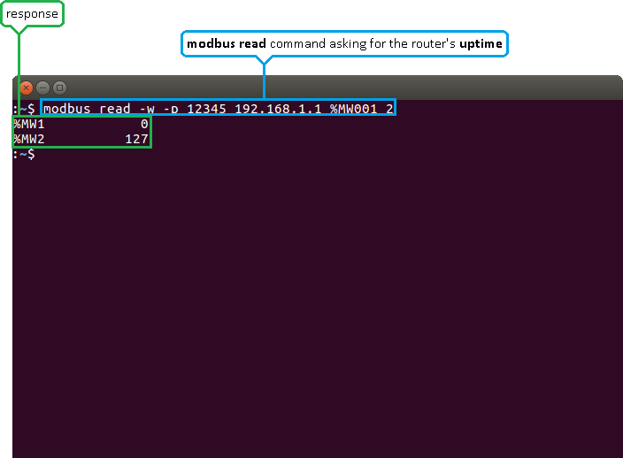
For the first example, lets use a modbus read command to attempt to obtain the router's uptime value in seconds. If you look back at the table above, you will see that the uptime value is stored in two registers starting from the first register, therefore:
$ modbus read -w -p 12345 192.168.1.1 %MW001 2
-w specifies the data type. In this case, unsigned 16 bit integers.
-p specifies the port number.
192.168.1.1 - the router's LAN IP address.
%MW001 specifies the register address.
2 - specifies how many registers should be read.
As you can see from the example above, the router returns the values stored in two registers: the first one and the second one. The values returned are presented in decimal form.
Interpreting the response
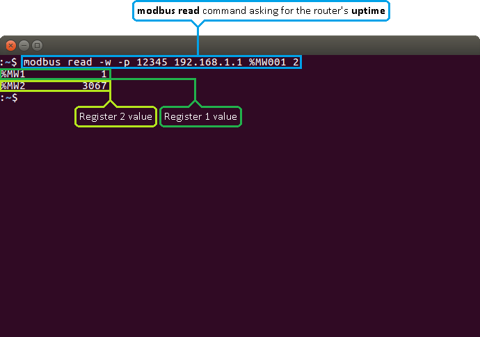
The values are returned in decimal and, if you add -D to the command, hexadecimal forms. Sometimes the answer is self-explanatory as in the example above. But, since a register only hold 2 bytes (16 bits) of information, the value stored in a register can't be higher than 65535 (216 -1). So what happens if the router's uptime is higher than that? Lets examine another example where the router's uptime is higher than 65535:
When the value climbs over 65535 the counter resets and the value held by the first register increases by 1. So one way to interpret the results would be to multiply the value in the first register by 65536 (216) and add it to the value of the second register: %MW1 * 65536 + %MW2. Which, following from the example above, would be: 1 * 65536 + 3067 = 68603 s or 19 hours 3 minutes 23 seconds.
However, while this works when calculating uptime values, it will not work for all parameters. The correct way to calculate the final values would be to first convert them to binary. As mentioned earlier in this chapter, a register holds 16 bits of information, which can be represented by a 16-digit long binary number. Following from the example above, the first register's value of 1 converted to binary would be 0000 0000 0000 0001 and the second register's value of 3067 would be 0000 1011 1111 1011. You can easily convert numbers from one numeral system to another using any online conversion tool:
The zeros at the beginning are added to represent the fact that the numbers are expressed in a 16-bit format. The next step is to add the two values, but not in the traditional sense. Instead, the value of the second register should act as an extension of the value of the first register or, to put it more simply, the values should be added up as if they were strings, i.e., 0000 0000 0000 0001 + 0000 1011 1111 1011 = 0000 0000 0000 0001 0000 1011 1111 1011. What happens here is that in this sum the first register's value of 1 shouldn't be considered as 1, but instead as 65536 (216) , which is the value of the 17th digit of a 32-bit long binary number. If you convert this value back to decimal, you will see that we get the same answer:
WAN IP address
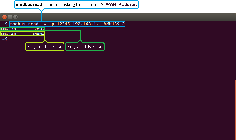
Lets examine a different, more complex example by issuing a request for the router's WAN IP address. If you look at the table above, you will see that the WAN IP address value is contained within the 139th and 140th registers. Therefore, we should specify the 139th address and read 2 registers from that address:
$ modbus read -w -p 12345 192.168.1.1 %MW139 2
An IPv4 address is divided into 4 segments. Each segment contains 8 bits (or 1 byte) of information:
So in order to get the WAN IP address from the response received, we'll need to convert the values of both registers to binary and split them into 8-bit segments. Lets do that with the values from the last example:
%MW139 2692 and %MW140 30404, which converted to binary would be: 2692 → 0000 1010 1000 0100 ; 30404 → 0111 0110 1100 0100.
As discussed earlier, we'll need to separate the two numbers into 8-bit segments to get the IP address:
Signal strength
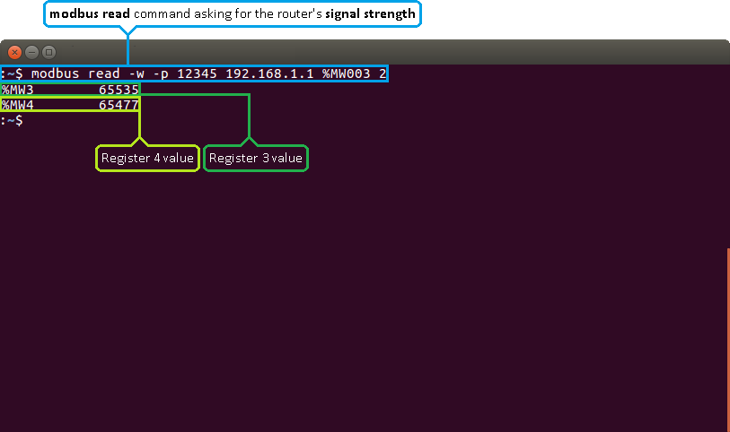
Yet another different example is Signal strength values, because they are negative. Lets examine an example of this to see how the values should be interpreted:
To change the sing of a binary number you must invert it add 1 to it. In the case of signal strength, you don't need both register values to do so, only the second one (register 4), which is, in our example, 65477. When converted to binary it's: 65447 → 1111 1111 1100 0101. Next, we'll to invert it and add 1:
The value we got is 0000 0000 0011 1011. When converted to decimal it becomes 59, so the final value is - 59
Text
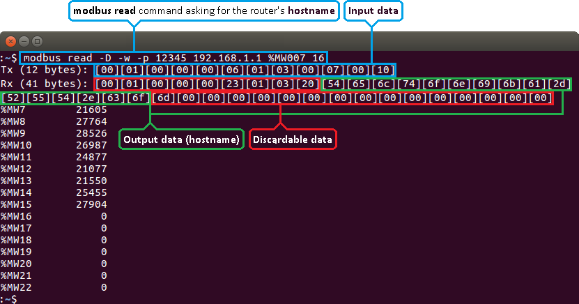
Some values like Hostname, Router name, Network type are represented as text in their original form, but are stored in registers as numbers. You can interpret these values the same way as all discussed before (by converting them to binary and then to text), but a simpler way would be to get them in hexadecimal form and then convert them to text. To do so, we'll have to add the -D parameter to the command. Lets do it by asking for the router's Hostname:
$ modbus read -D -w -p 12345 192.168.1.1 %MW007 16
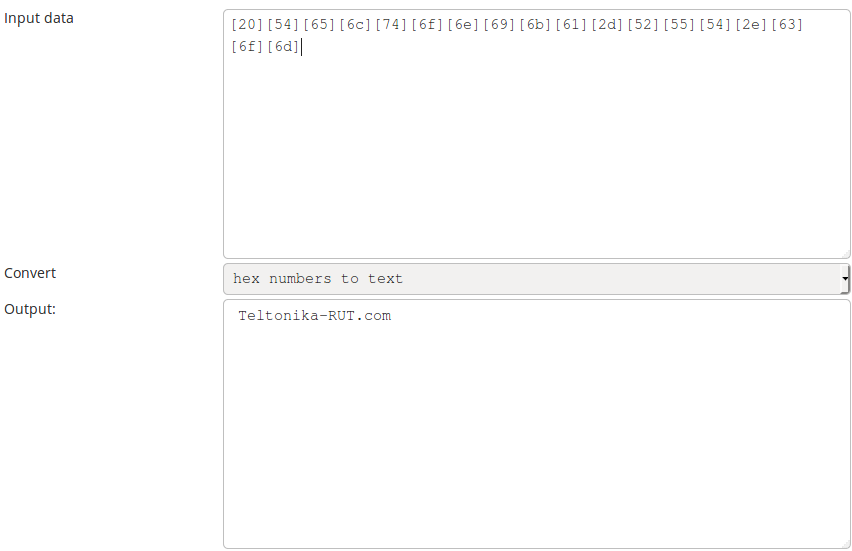
Ignore the first 9 segments and the last segments that contain only zeroes (highlighted in red). Copy the response (highlighted in green) and paste it into a hexadecimal to text (ASCII) converter:
Setting router values
The Modbus daemon also supports the setting of some system parameters. To accomplish this task the modbus write command is used. System related parameters and how to use them are described below. The register address specifies from which register to start writing the required values. All commands, except “Change APN”, accepts only one input parameter (more on changing APN can be found below).
Set Parameters
The Modbus daemon can also set some device parameters.
| value to set | register address | register number | register value | description |
|---|---|---|---|---|
| Hostname | 7 | 8 | Hostname (in decimal form) | Changes hostname |
| Device name | 71 | 72 | Device name (in decimal form) | Changes device name |
| Reboot | 206 | 207 | 1 | Reboots the router |
| Switch PIN 3 state | 324 | 325 | 1|0 | Toggles PIN 3 ON or OFF, when output is selected |
| Switch PIN 4 state | 325 | 326 | 1|0 | Toggles PIN 4 ON or OFF, when output is selected |
| Switch PIN 3 direction | 326 | 327 | 1|0 | Toggles PIN 3 direction between INPUT (0) or OUTPUT (1) |
| Switch PIN 4 direction | 327 | 328 | 1|0 | Toggles PIN 4 direction between INPUT (0) or OUTPUT (1) |
| Change LAN IP | 394 | 395 | IPv4 (in decimal form) | Changes device LAN IP |
As you can see most of the values are 0 and 1, 0 meaning OFF and 1 meaning ON. For example, if you want to turn WiFi OFF, this command should be used:
$ modbus write -w -p 12345 192.168.1.1 %MW203 0
If you want to turn WiFi ON, use this command instead:
$ modbus write -w -p 12345 192.168.1.1 %MW203 1
As you can see, the only difference is the digit at the end - 0 for OFF, 1 for ON. The same is true for all other parameters that accept only two input values.
In the case of SIM switch there are three values - 0, 1 and 2. 1 makes the first SIM card slot in use, 2 makes the second SIM card slot in use and 0 initiates a switc from the SIM card in use to the opposite SIM card. For example, to initiate a switch to the second SIM card the command should look like this:
$ modbus write -w -p 12345 192.168.1.1 %MW205 2
The reboot function only takes one value: 1. It simply reboots the router. To initiate a reboot, use this command:
$ modbus write -w -p 12345 192.168.1.1 %MW206 1
APN
APN is the only parameter that can accept more than one input value. For the APN parameter the number of input registers may vary. The very first byte of an APN command denotes the number of the SIM card for which the APN will be set. This byte should be set to 1 (in order to set the APN for SIM card number 1) or to 2 (in order to set the APN for SIM card number 2). The rest of the string should be entered one symbol at a time. Each symbol should be converted from ASCII (regular text) to decimal.
As an example lets try to change the router's first SIM card's APN to gprs.fix-ip.omnitel1.net:
$ modbus write -w -D -p 12345 192.168.1.1 %MW207 1 103 112 114 115 46 102 105 120 45 105 112 46 111 109 110 105 116 101 108 49 46 110 101 116
The value of the first byte is highlighted in blue and, in this case, it denotes that the APN value should be changed for the first SIM card. The value of the APN string itself is highlighted in green. Use an ASCII to Decimal online converter to convert individual letters to Decimal code.
External links
- Online unit converters:

