Configuring Modbus TCP Master: Difference between revisions
No edit summary |
|||
| Line 161: | Line 161: | ||
We can see that the slave device returns the registers master device has asked for. More information about how to understand the information we are getting from registers: '''[[Monitoring via Modbus]]''' | We can see that the slave device returns the registers master device has asked for. More information about how to understand the information we are getting from registers: '''[[Monitoring via Modbus]]''' | ||
==Alarms== | |||
Alarms are a way of setting up automated actions when some Modbus values meet user specified conditions. To configure these alarms we click on ''''Alarms'''' button: | |||
[[File:AddedSlaveDevice.png]] | |||
The table below provides information on fields that this page contains: | |||
==Clone Slave Configuration== | |||
Revision as of 14:17, 11 September 2019
Summary
Modbus TCP Master section is used for configuring your router as a master device and other routers configured in this section as slave devices. A Modbus TCP master device can then request data from these Modbus TCP slaves. Firstly, let's configure our second router which will be acting as a slave device.
Configuring Modbus TCP slave device
In this example we would be configuring our slave device to have 192.168.1.2 internal IP address. This can be done by changing the IP address parameter in Network->LAN page:
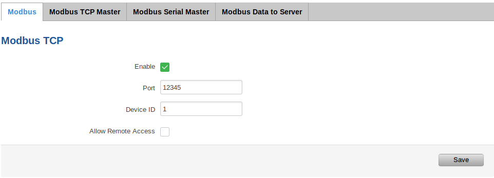
Now we need to enable Modbus service for this slave device as we will open specific port for letting through TCP communications (it is also possible to 'Allow remote access' if we wish to access this router from external WAN using it's public IP). This is done in Services->Modbus page:
Adding new slave device
On master device (in this example master device has 192.168.1.1 internal IP address) open Services->Modbus->Modbus TCP Master. To add a new slave, enter a custom name, slave's ID, IP address and port and click the "Add" button:
Note: Slave's ID, IP and Port should be exactly the same as configured in the slave's device Services->Modbus page
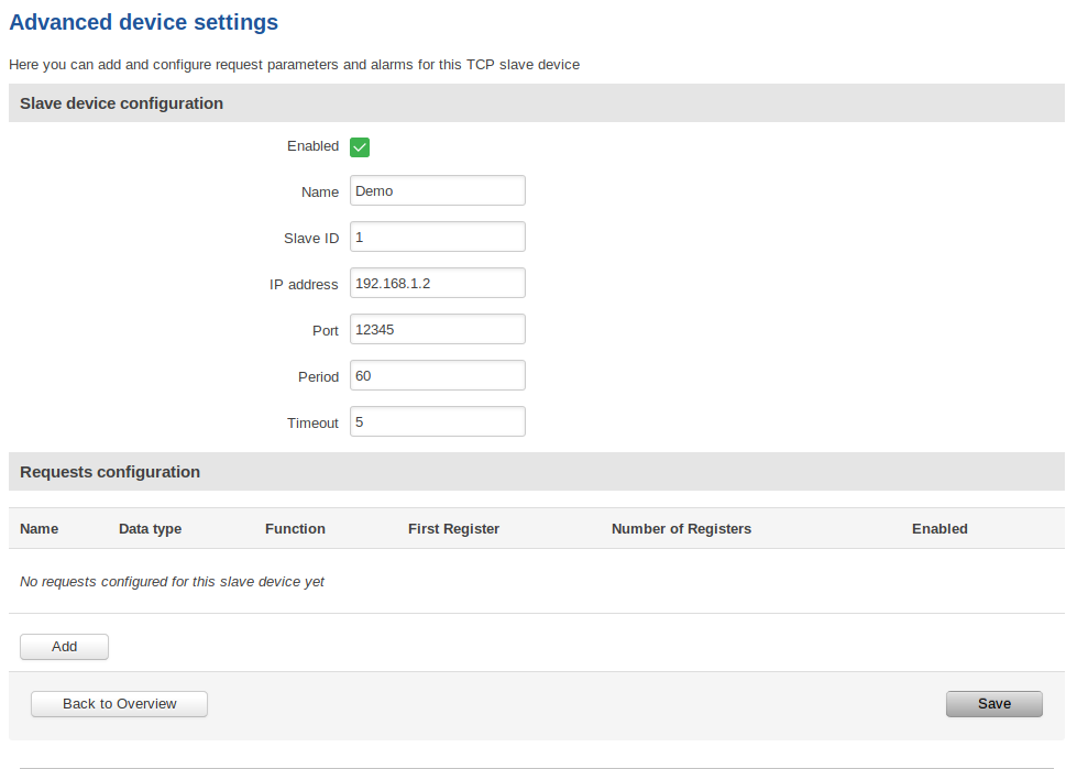
After clicking the 'Add' button you will be redirected to advanced slave's configuration page:
| Field | Value | Description |
|---|---|---|
| Enabled | yes | no; default: no | Turns communication with the slave device on or off. |
| Name | string; default: none | Slave device's name, used for easier management purposes. |
| Slave ID | integer [0..255]; default: none | Slave ID. Each slave in a network is assigned a unique identifier ranging from 1 to 255. When the master requests data from a slave, the first byte it sends is the Slave ID. When set to 0, the slave will respond to requests addressed to any ID. |
| IP address | ip; default: none | Slave device's IP address. |
| Port | integer [0..65535]; default: none | Slave device's Modbus TCP port. |
| Period | integer [1..6400]; default: none | Interval at which requests are sent to the slave device. |
| Timeout | integer [1..30]; default: none | Maximum response wait time. |
Enable this slave's configuration by clicking on the checkbox and enter the timeout in seconds. Click Save.
Now the slave device is added to the Modbus TCP Master section but we need to test if it is working.
Testing
For testing if the functionality is working we can configure a request. A Modbus request is a way of obtaining data from Modbus slaves. The master sends a request to a slave specifying the function code to be performed. The slave then sends the requested data back to the Modbus master. You can create a maximum of 64 request configurations for each slave device.
We click 'Edit' button in the slave device's configuration.
By clicking the 'Add' button in the Requests configuration section we will be able to configure a new request. Let's say that in our case we are interested in the System Uptime parameter which is located in the first 2 registers of our device (more about the parameters and their registers we can get or set using Modbus service: RUT955 Modbus). Here is how our request should look like for this purpose:
| Field | Value | Description |
|---|---|---|
| Name | string; default: Unnamed Parameter | Request name. Used for easier management purposes. |
| Data type | 8bit INT | 8bit UINT | 16bit INT, high byte first | 16bit INT, low byte first | 16bit UINT, high byte first | 16bit UINT, low byte first | 32bit float, Byte order 1,2,3,4 | 32bit float, Byte order 4,3,2,1 | 32bit float, Byte order 2,1,4,3 | 32bit float, Byte order 3,4,1,2; default: 16bit INT, high byte first | How read data will be stored. |
| Function | 1 | 2 | 3 | 4 | 5 | 6 | 15 | 16; default: 3 | A function code specifies the type of register being addressed by a Modbus request. The codes represent these functions:
|
| First Register | integer [0..65535]; default: 1 | First Modbus register from which data will be read. |
| Number of Registers | integer [1..2000]; default: none | Number of Modbus registers that will be read during the request. |
| Enabled | yes | no; default: no | Turns the request on or off. |
| Test | - (interactive button) | Generates a Modbus request according to given parameters in order to test the request configuration. You must first save the configuration before you can use the Test button. |
| Delete | - (interactive button) | Deletes the request. |
| Add | - (interactive button) | Adds a new request configuration. |
Note: During the time this article is written, we need to 'Save' the configuration first before clicking the 'Test' button. This will redirect you to the Modbus TCP Master page and you will need to click 'Edit' button again to try and test the functionality of this request.
Now by clicking the 'Test' button we can get the System Uptime value from the first 2 registers:
We can see that the slave device returns the registers master device has asked for. More information about how to understand the information we are getting from registers: Monitoring via Modbus
Alarms
Alarms are a way of setting up automated actions when some Modbus values meet user specified conditions. To configure these alarms we click on 'Alarms' button:
The table below provides information on fields that this page contains:


