IPsec configuration examples
Introduction
In computing, Internet Protocol Security (IPsec) is a secure network protocol suite of IPv4 that authenticates and encrypts the packets of data sent over an IPv4 network. IPsec includes protocols for establishing mutual authentication between agents at the beginning of the session and negotiation of cryptographic keys to use during the session. IPsec can protect data flows between a pair of hosts (host-to-host), between a pair of security gateways (network-to-network), or between a security gateway and a host (network-to-host). Internet Protocol security (IPsec) uses cryptographic security services to protect communications over Internet Protocol (IP) networks. IPsec supports network-level peer authentication, data-origin authentication, data integrity, data confidentiality (encryption), and replay protection.
This article provides an extensive configuration example with details on how to create a tunnel connection between two IPsec instances, both of which configured on RUTxxx routers.
Configuration overview and prerequisites
Before we begin, let's overview the configuration that we are attempting to achieve and the prerequisites that make it possible.
Prerequisites:
- Two RUTxxx routers of any type (excluding RUT850)
- Both routers must have a Public Static or Public Dynamic IP addresses
- At least one end device (PC, Laptop, Tablet, Smartphone) to configure the routers
- (Optional) A second end device to configure and test remote LAN access
There will be two IPsec configuration schemes presented. Although the second scheme is only an extension of the first one. Therefore, to configure the second scheme, you will have to configure the first as well.
configuration scheme 1:
The figure above above depicts two RUTxxx routers (RUT1 and RUT2) connected by an IPsec tunnel via the Internet.
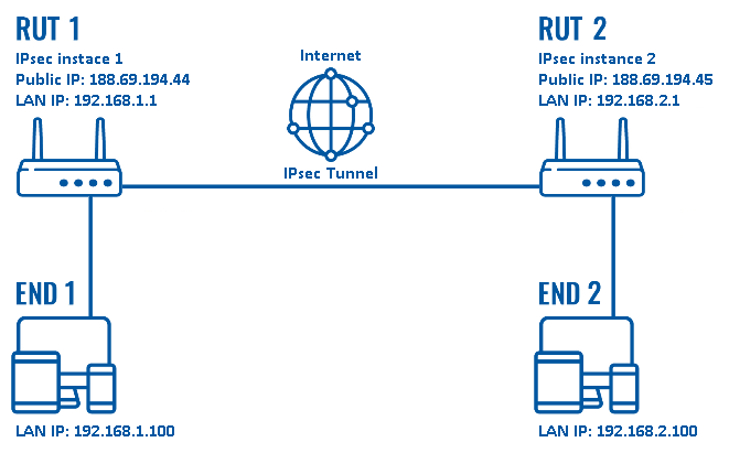
configuration scheme 2:
As mentioned earlier, configuration scheme 2 (figure above) is an extension of configuration scheme 1. While configuration scheme 1 only depicts a connection between two IPsec instances, you can see that configuration scheme 2 additionally contains two end devices (END1 and END2), each connected to a separate router's LAN. When this scheme is realized, not only will the two routers be able to communicate with each other, but the end devices will also be reachable to one another and from each router.
It should also be noted the connection type used is Tunnel and not Transport. Tunnel protects the internal routing information by encrypting the IP header of the original packet. The original packet is encapsulated by a another set of IP headers. Transport encrypts only the payload and Encapsulating Security Payload (ESP) trailer; so the IP header of the original packet is not encrypted. Transport mode is usually used when another tunneling protocol (such as GRE, L2TP) is used to first encapsulate the IP data packet, then IPsec is used to protect the GRE/L2TP tunnel packets.
Tunnel is more widely implemented in site-to-site VPN scenarios and supports NAT traversal, that's why we chose it for the example.
Router configuration
If you have familiarized yourself with the configuration schemes and have all of the devices in order, we can start configuring the routers using instructions provided in this section.
Basic tunnel
First of, lets configure a simple connection between two IPsec instances, i.e., RUT1 and RUT2 as described above in configuration scheme 1.
- Login to the router's WebUI and go to Services → VPN → IPsec. Enter a custom name (for this example we use RUT1) for the IPsec instance click the "Add" button:
- Click the "Edit" button located next to the newly created instance:
- You will be redirected to the instance's configuration window. From here we will discuss how to configure both instances (RUT1 and RUT2). Creating a second instance is analogous to how we created the first one - just login to the second router and repeat the first two steps. Although not mandatory, we recommend that you use a distinct name for the second instance (for this example we use RUT2) for easier management purposes.
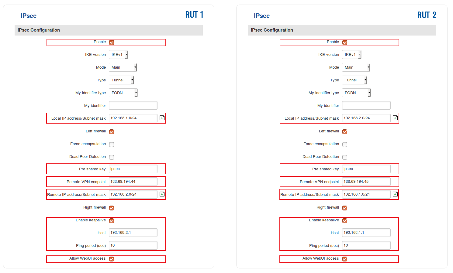
The specifics of both configurations are described in the figure below:
- Below are explanations of the parameters highlighted in the figure above. Other parameters (not highlighted) are defaults. You can find descriptions for these parameters in the VPN manual page, IPsec section.
- Enable - enables the IPsec instance
- Local IP address/Subnet mask - LAN IP address/Subnet mask of the router on which the IPsec instance is configured
- Pre shared key - a shared password used for authentication between the peers. The value of this field must match on both instances
- Remote VPN endpoint - the Public IP address of the opposite router
- Remote IP address/Subnet mask - LAN IP address/Subnet mask of the opposite router
- Enable keepalive - enables the tunnel's keep alive function. When enabled, the instance sends ICMP packets to the specified host at the specified frequency. If no response is received, the instance attempts to restart the connection
- Host - hostname or IP address to which ICMP packets will be sent to. Best to use a hostname/IP address belonging to the opposite instance's LAN. For this example we just use the other router's LAN IP address
- Ping period (sec) - the period (in seconds) at which ICMP packets will be sent to the specified host
- Allow WebUI access - when checked, allows WebUI access for hosts from the opposite instance
NOTE: remember to replace certain parameter values (like IP addresses) with your own relevant data.
- The last step in configuring the IPsec instances is Phase settings. For this example we left the default Phase settings. If you're planning to change Phase settings, make sure they match with the Phase settings (both Phase 1 and Phase 2) of the incoming connection:
When you're finished with the configuration, don't forget to click the "Save" button.
Remote LAN access
Once your IPsec tunnel is operational, you can configure remote access to LAN devices via the tunnel as referenced in configuration scheme 2. This section provides a description on how to do just that.
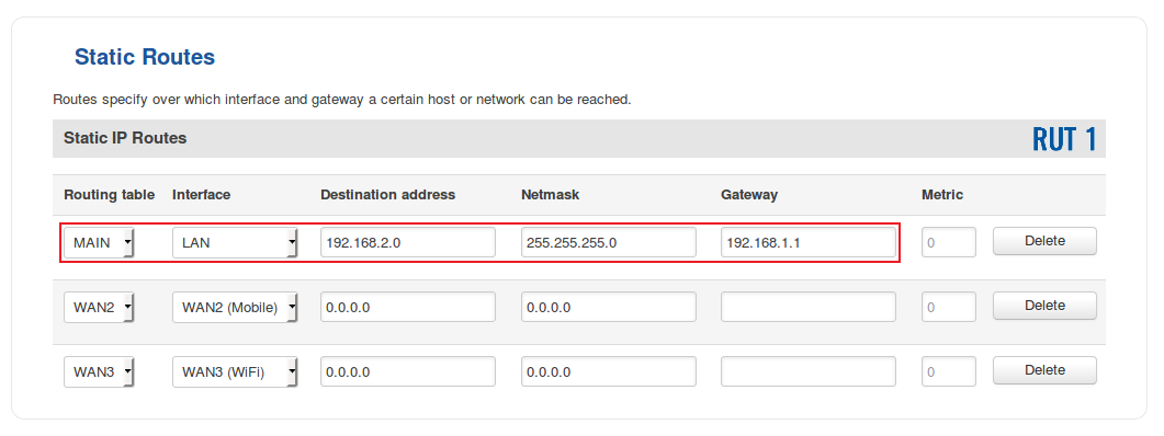
- In order for the remote LAN access to work, we'll need to add a couple of static routes - one in each router. Login to a router's WebUI and navigate to Network → Routing → Static Routes. Continuing our example, below is figure depicting the static route configuration for RUT1:
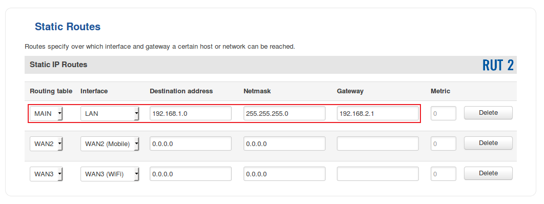
- And for RUT2:
- To sum up, for our current purposes select MAIN Routing table and LAN interface in both routers; under Destination address, specify the LAN address of the opposite router; under Netmask, specify 255.255.255.0 unless your configuring a different size network (more on Netmasks here); under Gateway, specify the current router's LAN IP address; you can leave the Metric as 0 unless your own specific configuration requires otherwise.
Testing the setup
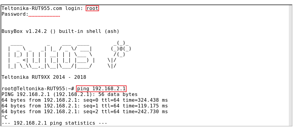
If you've followed all the steps presented above, your configuration should be finished. But as with any other configuration, it is always wise to test the set up in order to make sure that it works properly. In order to test an IPsec connection, login to one of the routers' WebUI and go to Services → CLI. Login with user name: root and the router's admin password. From there you should then be able to ping the opposite instance's LAN IP address. To use a ping command, type ping <ip_address> and press the "Enter" key on your keyboard:
You can also test if LAN access is working the same way. Instead of pinging the opposite instance's LAN IP address, ping one of the end device's IPs. One common issue that can be encountered here is that the end devices might need their DHCP leases renewed. There are many methods of accomplishing this, but the easiest and most accessible way is to simply disconnect and reconnect the LAN cable to device or the router that it's connected to.
If the ping requests are successful, congratulations, your set up works! If not, we suggest that you review all steps once more.
See also
- Other types of VPNs suported by RUTxxx devices:


