L2TP configuration examples
Introduction
Layer 2 Tunneling Protocol (L2TP) is a tunneling protocol used to support virtual private networks (VPNs) or as part of the delivery of services by ISPs. It does not provide any encryption or confidentiality by itself. Rather, it relies on an encryption protocol that it passes within the tunnel to provide privacy.
This article provides an extensive configuration example with details on how to create a connection between an L2TP Server and Client, both of which configured on RUTxxx routers. If you wish to learn how to encrypt the traffic of your L2TP tunnel, we suggest you take a look at our L2TP over IPsec article.
Configuration overview and prerequisites
Before we begin, let's overview the configuration that we are attempting to achieve and the prerequisites that make it possible.
Prerequisites:
- Two RUTxxx routers of any type (excluding RUT850)
- A SIM card with a Public Static or Public Dynamic IP address for the L2TP Server
- An end device (PC, Laptop, Tablet, Smartphone) to configure the routers
Configuration scheme:
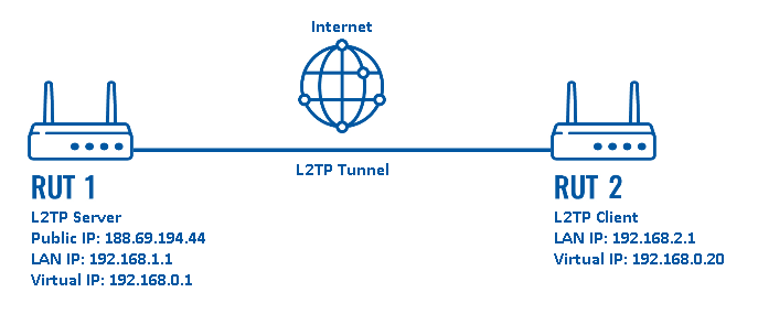
As indicated by the figure above, the configuration we are trying to achieve here is very basic: it concerns two RUTxxx routers - RUT1 and RUT2. One functions as an L2TP Server, the other - an L2TP Client. They are connected into a virtual network via an L2TP Tunnel.
Router configuration
If you have familiarized yourself with the configuration scheme and have all of the devices in order, we can start configuring the routers using instructions provided in this section.
L2TP Server (RUT1)
As mentioned in the prerequisites section, the router that acts as the server must have a Public Static or Public Dynamic IP address (more information on the subject can be found here). If that is in order, we should start configuring the server.
- Login to the router's WebUI and go to Services → VPN → L2TP. Select Role: Server, enter a name for the new instance and click the "Add" button:
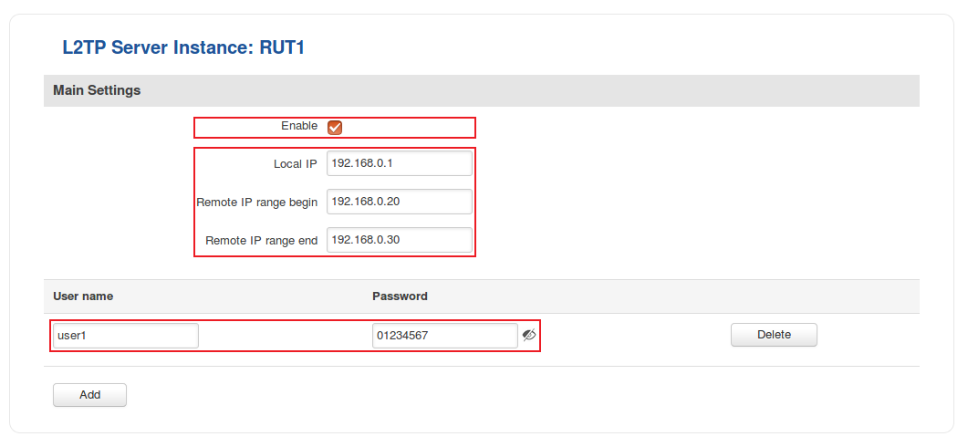
- Click the "Edit" button located to the right of the newly created L2TP Server to enter the instance's settings window. The configuration is fairly simple, just remember to Enable the instance:
- The rest of the parameters are user preferential so you should set them as you see fit. A short explanation on these parameters is provided below:
- Local IP defines the server's virtual IP address
- Remote IP range parameters define the range of virtual IP addresses that will be assigned to connecting clients
- User name and Password parameters define a client's authentication info
Once you're done setting these parameters don't forget to click the Save button.
Setting up a proxy (optional)
Web proxies facilitate access to content on the World Wide Web and provide anonymity for the connecting clients. This is because the web proxy relays connected clients' requests through itself. Thus, the clients effectively "adopt" the server's Public IP address.
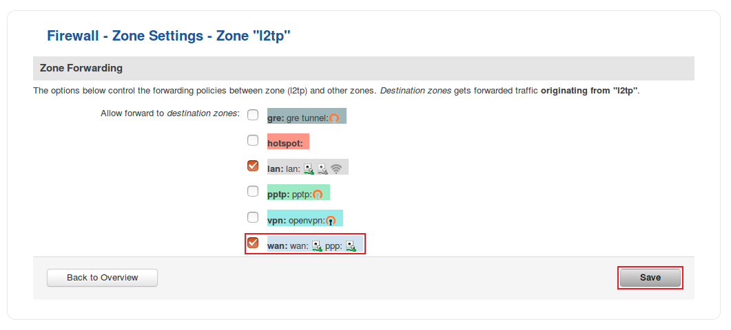
- If you plan on using the L2TP Server as a web proxy, you will need to edit one preexisting Zone Forwarding rule in addition to the server configuration. In the router's WebUI, go to Network → Firewall → General Settings, locate l2tp in the Zone Forwarding table and click the "Edit" button next to it:
- After this you will be redirected to the L2TP Zone Settings page where you will need to place a check mark next to the wan destination zone:
After you save the changes your L2TP Server will now also act as a web proxy.
NOTE: this step is purely optional and should be used only if you plan on using your server as a web proxy for your clients. If you are just planning to use L2TP to connect multiple remote networks into a single virtual network, you should probably skip this step.
L2TP Client (RUT2)
- Now let's configure the L2TP Client. Login to the router's WebUI and go to Services → VPN → L2TP. Select Role: Client, enter a name for the new instance and click the "Add" button:
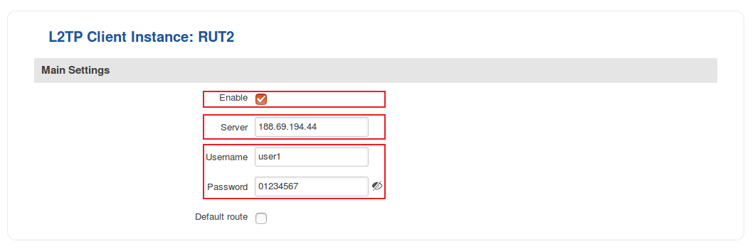
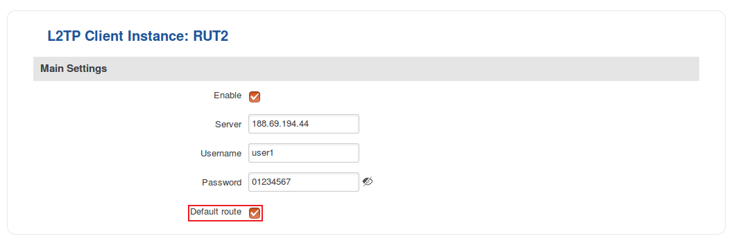
- Click the "Edit" button located to the right of the newly created L2TP Client to enter the instance's settings window. In the settings window, Enable the L2TP instance, specify the server's Public (WAN) IP address and the client's authentication info as specified in the server's configuration:
Once this is done, don't forget to save the changes.
- Optional: if you plan on using the server as a web proxy, you should also enable the Default route option in the client's configuration:
Testing the setup
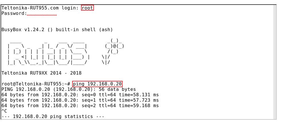
If you've followed all the steps presented above, your configuration should be finished. But as with any other configuration, it is always wise to test the setup in order to make sure that it works properly. In order to test an L2TP connection, login to one of the routers' WebUIs and go to Services → CLI. Login with user name: root and the router's admin password. You should then be able to ping the opposite instance, i.e., if you logged in to the server's CLI, you should be able to ping the client's virtual IP address, and vice versa. To use a ping command, type ping <ip_address> and press the "Enter" key on your keyboard:
If the ping requests are successful, congratulations, your setup works! If not, we suggest that you review all steps once more.
If you're using the server as a web proxy, end devices connected to the L2TP client router should have the Public IP address of the L2TP server. You can visit this website to check the Public IP address: http://www.whatsmyip.org/
See also
- L2TP over IPsec
- Other types of VPNs suported by RUTxxx devices:

