TRB141 1-Wire Setup/Configuration
The information on this page is updated in accordance with 00.07.04 firmware version.
Introduction
Inputs and outputs are used for monitoring and controlling a connected device or receiving signals from that device in order to trigger certain events.
1-Wire is a voltage-based digital system that works with two contacts, data and ground, for half-duplex bidirectional communication. Compared to other serial communication systems such as I2C or SPI, 1-Wire devices are designed for use in a momentary contact environment.
In this chapter, we will set up and configure the 1-Wire sensor with TRB141.
Prerequisites
- TRB141
- 1-Wire sensor
- If 1-Wire doesn't have its Wires(Like Dallas DS1820 used in this example) you will need additional wires to connect the sensor to TRB141
Connecting 1-Wire Sensor with TRB141
First of all we will connect the 1-Wire sensor with TRB141, for this example, I will be using two different 1-Wire sensors Dallas DS1820 and Dallas DS1922. Before we proceed with the connection, make sure you know how your 1-Wire sensor has to be connected, or open your 1-Wire sensor data sheet to reference where each wire should be connected.
DS1820 connection
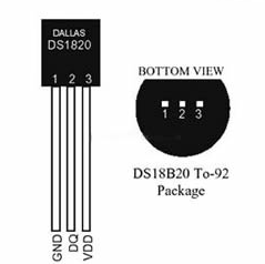
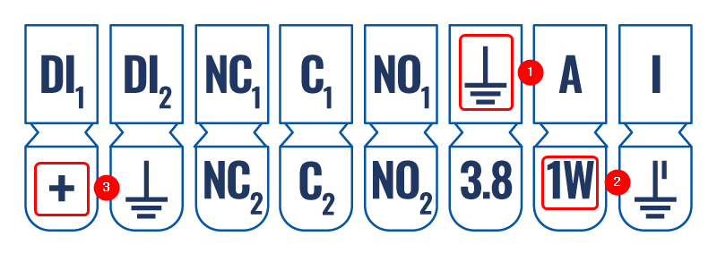
The wiring for DS1820 can be seen in the picture provided below. We will connect the 1st wire to TRB141, the second wire to the 1-Wire pin on TRB141, and the 3rd wire to the + pin. Please see the Wiring of DS1820 and Pinout of TRB141 on which pins should be connected.
Wiring:
Pinout:


