IBGP configuration example
The information on this page is updated in accordance with the 00.07.06.10 firmware version .
Introduction
BGP, or Border Gateway Protocol, is a fundamental routing protocol used in large-scale networks, particularly the internet, to exchange routing and reachability information among autonomous systems (ASes). This article provides a guide on how to configure iBGP or internal Border Gateway routing which uses one autonomous system on our two routers.
Configuration overview and prerequisites
Prerequisites:
- Routers must be connected through WAN-WAN connection
- At least two end devices (PCs, Laptops) to configure the routers and test the set up
- Both routers must be on "Advanced mode"

Topology
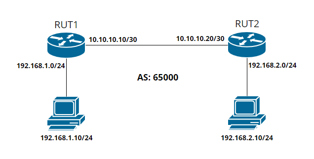
iBGP Configuration
RUT1 BGP Configuration
Navigate to Network -> Routing -> Dynamic routes -> BGP. Enable "BGP - Global Settings" and "vty".

On BGP Instance tab configure it like this:
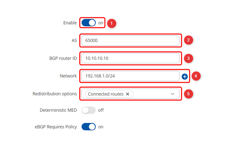
1. Enable - on
2. AS - 65000 (it must be the same on both routers)
3. BGP router ID - 10.10.10.10 (RUT1 WAN IP)
4. Network - 192.168.1.0/24 (RUT1 LAN subnet)
5. Redistribution options - Connected routes
Go to BGP peers tab and add new instance. For Name write any name you desire and press Add.

On popped up window select these options:
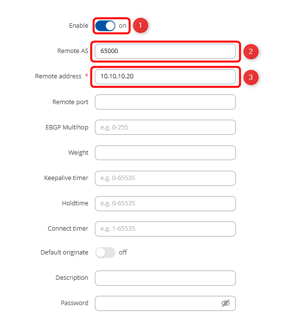
1. Enable - on
2. AS - 65000 (it must be the same on both routers)
3. Remote address - 10.10.10.20 (RUT2 WAN IP)
RUT2 BGP Configuration
For RUT2, the configuration is very similar, all we need to do is just change the BGP router ID to 10.10.10.20, Network to 192.168.2.0/24 on the BGP Instance, and the Remote address to 10.10.10.10 on the Peer Configuration.
BGP Instance should look like this:
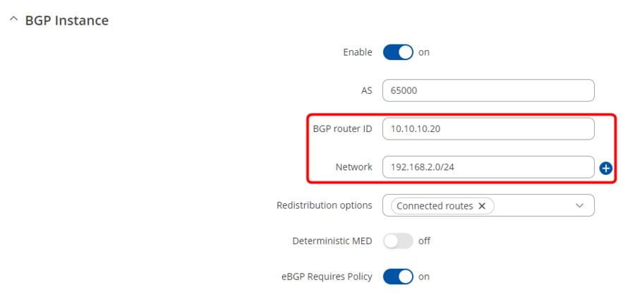
And Peer Configuration like this:

Firewall Zones
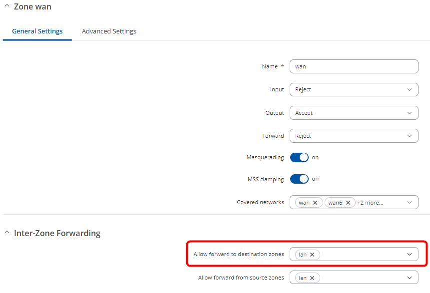
Now we can reach only routers by them self to reach their whole network we need to edit Firewalls WAN Zone to add lan on forward to destination zones field.
On both routers navigate to Network -> Firewall -> General Settings -> Zones and press edit on wan zone.

On popped up window add lan on Allow forward to destination zones field and press
Testing the setup
If you have followed the steps correctly, the configuration should be complete. Here are the results you can expect to receive:
PC1 to PC2:
Pinging 192.168.2.10 from 192.168.1.10 with 32 bytes of data:
Reply from 192.168.2.10: bytes=32 time=3ms TTL=62
Reply from 192.168.2.10: bytes=32 time=5ms TTL=62
Reply from 192.168.2.10: bytes=32 time=5ms TTL=62
Reply from 192.168.2.10: bytes=32 time=3ms TTL=62
PC2 to PC1:
Pinging 192.168.1.10 from 192.168.2.10 with 32 bytes of data:
Reply from 192.168.1.10: bytes=32 time=9ms TTL=124
Reply from 192.168.1.10: bytes=32 time=3ms TTL=124
Reply from 192.168.1.10: bytes=32 time=5ms TTL=124
Reply from 192.168.1.10: bytes=32 time=5ms TTL=124
See also
External links
https://frrouting.org/ - additional information about FRRouting that our device routing is based on.
