Domnev
The information on this page is updated in accordance with the 00.07.4 firmware version .
Summary
In this guide, the MQTT Serial Gateway function will be configured using third-party MQTT Broker services (in this example, Flespi.io).
Configuration overview & prerequisites
- Two devices with serials ports - one acts as Modbus RTU Master, another as Modbus RTU Slave;
- Flespi.io account to act as an MQTT Broker/Publisher/Subscriber (for first configuration example);
Configuration using flespi.io as MQTT Broker
Configuring RUT955 MQTT Gateway
Go to Services → Modbus → MQTT Gateway and there:
- Enable the instance;
- Enter Host (copied from flespi connection settings without 'wss://' and port);
- Enter Username (Copied from flespi Connection settings generated token);
- Enter Password.
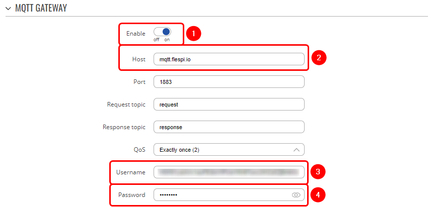
Note: Everything else can be left as default or changed according to your needs.
Configuring RUT955 Serial Gateway
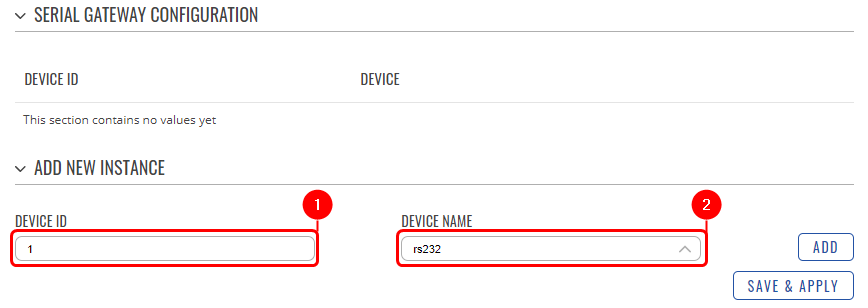
Under the MQTT Gateway configuration, create the Serial Gateway:
- Enter the desired device ID;
- Select the desired serial interface.
Configuring Flespi.io MQTT Broker
Log in or create an account on https://flespi.io;
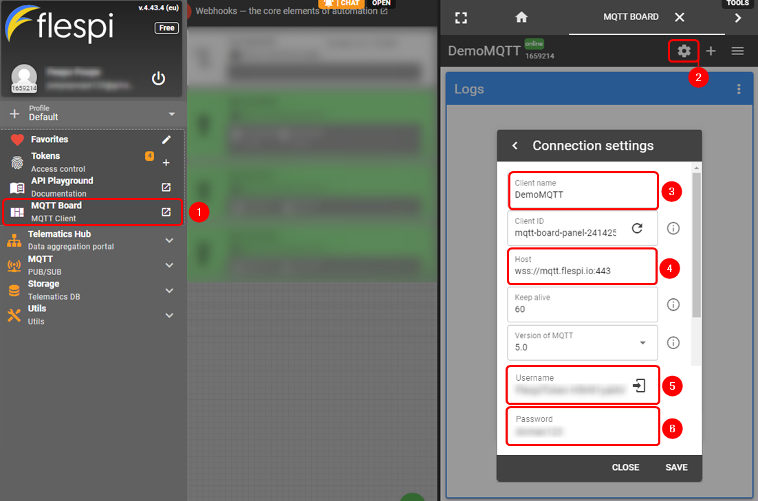
- Navigate to MQTT Board on the left side menu;
- On the right-hand panel, top right corner, next to the name of the MQTT board, press the cogwheel-looking icon to open Connection Settings;
- In the opened window, press "Get flespi token" to generate a username;
- Enter the Client name;
- Copy the Host address;
- Copy Username;
- Create a password.
Once done, save all the changes.
Message format for MQTT publisher
Modbus request data sent in the MQTT payload should be generated in accordance with the following format:
1 <COOKIE> <SERIAL_DEVICE_ID> <TIMEOUT> <SLAVE_ID> <MODBUS_FUNCTION> <FIRST_REGISTER> <REGISTER_COUNT>
The table below explains what each option means:
| 1. Format version | 1 |
| 2. Cookie | from 0 to 264 -1 |
| 3. Serial device ID | a string used to identify a serial device. Must match with Device ID field in MQTT Gateway page Serial gateway configuration section |
| 4. Timeout | timeout for Modbus connection, in seconds. Range [1..999]. |
| 5. Slave ID | Indicates to which slave request is sent |
| 6. Modbus function | Modbus task type that will be executed. Possible values are:
|
| 7. First register | number (not address) of the first register/coil/input (in range [1..65536]) from which the registers/coils/inputs will be read/written to. |
| 8. Registry count |
Examples
Modbus parameters are held within registers. Each register contains 2 bytes of information. For simplification, the number of registers for storing numbers is 2 (4 bytes), while the number of registers for storing text information is 16 (32 bytes).
The register numbers and corresponding system values can be found in this article.
| Setting relay (on) (Relay address is 202, which means 'Number of first register will be 203) | 1 1 1 1 1 6 203 1 |
| Getting temperature | 1 1 1 1 1 3 6 2 |
Testing MQTT Publisher and Subscriber on flespi.io
Adding Flespi Subscriber
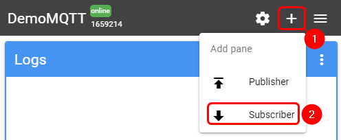
To test the Modbus Serial Gateway functionality, log into your Flespi account → MQTT Board and add a Subscriber:
- Press '+' button on the top right corner
- Select 'Subscriber'
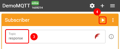
- In the topic field enter 'response'
- Press 'Subscribe' button
Adding Flespi Subscriber
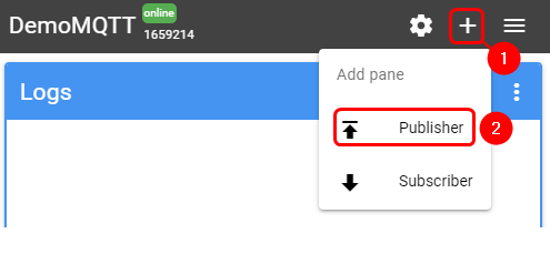
Also, you will need to add a Publisher:
- Press '+' button on the top right corner
- Select 'Publisher'
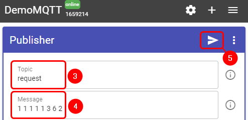
- In the topic field enter 'request'
- In the message field enter message, for this example 'Getting temperature' is used
- Press 'Publish' button
Flespi Subscriber output
Check the response in the 'Subscriber' tab, you should receive a message similar to the one below.
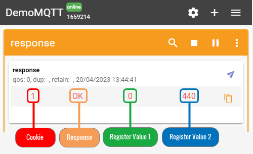
In the output, we can see that router's temperature is 44 degrees Celsius.

