TSW100 Spatial Measurements & Weight
This page contains spatial measurement and weight information for TSW100 devices. The drawings provided here are intended to help approximate the size of the device before installation.
Figures presented below display the device's measurements from several different angles and of various elements (cables, connectors, etc.) that are located on or protruded out of the device. All measurements are specified in millimetres (mm).
Click here to download TSW100 measurements as PDF.
Main measurements
W x H x D dimensions for TSW100:
|
115 x 32 x 95 mm 173 x 71 x 148 mm |
*Housing measurements are presented without antenna connectors and screws; for measurements of other device elements look to the sections below.
3D view
You can inspect the device's 3D model by downloading the archive and extracting 3D files:
Viewing 3D PDF file
To view and interact with the 3D PDF file, please follow these steps:
- Download the file.
- Open the file with a PDF viewing program; for this overview Adobe Acrobat Reader DC version 2020.012.20043 was used. Do not use your browser to open the file, because you will see only a blank page.
- It is that likely 3D content viewing will be disabled by default. If that is the case, you will see a blank page with a warning.
Click on Options and select either to trust the document once or always. Pick a choice in accordance with your preferences.
- After this you should be able to see and interact with the 3D model. For easier navigation, click the right mouse button and select Show Model Tree and look to the left side. You should see a list with all parts where you can pick and choose what you want to be displayed on your screen.
- If a warning message was not displayed but you still cannot view the 3D PDF file, please try the following:
- Go to Edit → Preferences → 3D & Multimedia.
- Tick the Enable playing 3D content checkbox.
- If you cannot locate 3D content options, please update your PDF viewer to the latest version.
Viewing GLB file
To open a GLB file, use the 3D Viewer application, available as a free download on the Microsoft Store for Windows. After installing the application, double-click the GLB file or open it directly from the 3D Viewer interface.
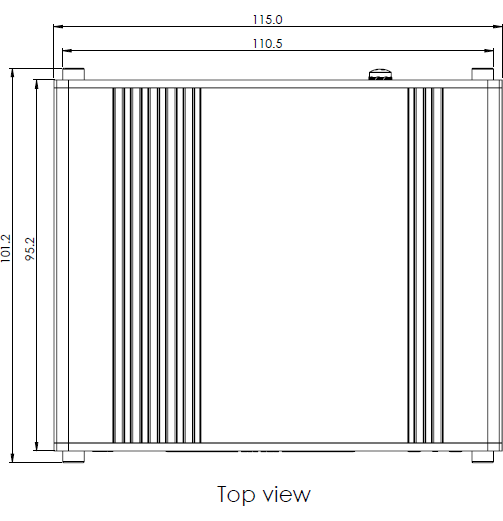
Top view
The figure below depicts the measurements of TSW100 and its components as seen from the top of the device:
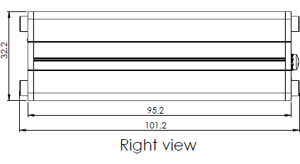
Right view
The figure below depicts the measurements of TSW100 and its components as seen from the right side:
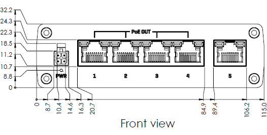
Front view
The figure below depicts the measurements of TSW100 and its components on the front panel:
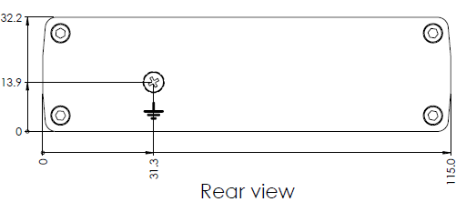
Rear view
The figure below depicts the measurements of TSW100 and its components on the back panel:
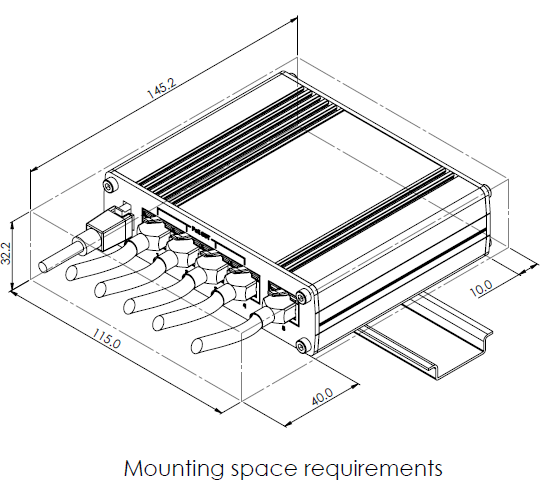
Mounting space requirements
The figure below depicts an approximation of the device's dimensions when cables and antennas are attached:
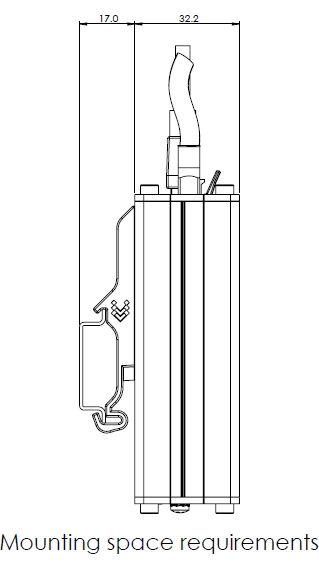
DIN rail
The figure below depicts approximate space requirements for DIN rail mounting:
Weight
|
350 g 63 g 780 g |

