RUTX DMVPN
The information in this page is updated in accordance with 00.07.19.2 firmware version.
Introduction
Dynamic Multipoint VPN (DMVPN) is a dynamic tunneling form of a virtual private network (VPN) supported on Cisco routers. This article contains step-by-step instructions on how to configure DMVPN between a "HUB" and two "Spokes" using RUTXxx routers.
Prerequisites
You will need:
- At least two RUTxxx routers
- A PC to configure the routers
- HUB has to be reachable from spokes (HUB must have Public IP address, or has to be in the same WAN network as Spokes)
Note: If you are using a RUT2xx or RUT9xx device, you will need to install the “BGP daemon, DMVPN, and NHRP daemon” packages.
Configuration scheme

Spoke configuration
This section contains information on how to configure DMVPN Spokes. Firstly, we'll configure the DMVPN instance to make the connection possible. Then we'll set the Border Gateway Protocol (BGP) parameters as our dynamic routing solution.
Note: at the moment, BGP is the only stable dynamic routing solution that can work with DMVPNs.
STEP 1: Connect to router's WebUI, go to Services > VPN > DMVPN. Enter a name for your DMVPN instance, click ADD and when instance appears in DMVPN CONFIGURATION field, click Edit.

STEP 2: Configure DMVPN settings.

- Enable instance.
- Select Working mode (Spoke).
- Enter HUB Address (HUB WAN IP).
- Select Tunnel source (select your WAN interface).
- Write Local GRE interface IP address (create GRE tunnel IP address or just use the same as in the example).
- Write Remote GRE interface IP address (create GRE tunnel IP address or just use the same as in the example).
- Add GRE MTU (largest PDU size of any single transaction).
- (optional) Write Inbound and outbound keys (Spoke keys should be mirrored from the hub – outbound becomes inbound and et cetera).
- Add Pre-shared key (it must match HUB and other Spokes).
- (optional) Write IKE lifetime (how long the keying channel of a connection should last before being renegotiated). Do this in PHASE 1 and PHASE 2. They should match on HUB and spokes.
- Leave everything else as default and click Save & Apply.
STEP 3: Go to Network > Routing > Dynamic Routes > BGP, enable BGP and vty, and either create a new BGP instance or modify the default general instance:

STEP 4: Configure BGP instance settings:

- Enable instance.
- Add AS (Autonomous system name, it must match on all of the devices, including other Spokes and hub).
- Write BGP router ID (SPOKE GRE Tunnel IP).
- Add Network (SPOKE LAN network IP with subnet mask).
- Select Redistribution options. (NHRP routes)
- Repeat steps 6 to 10 for the hub and for each of the other spokes.
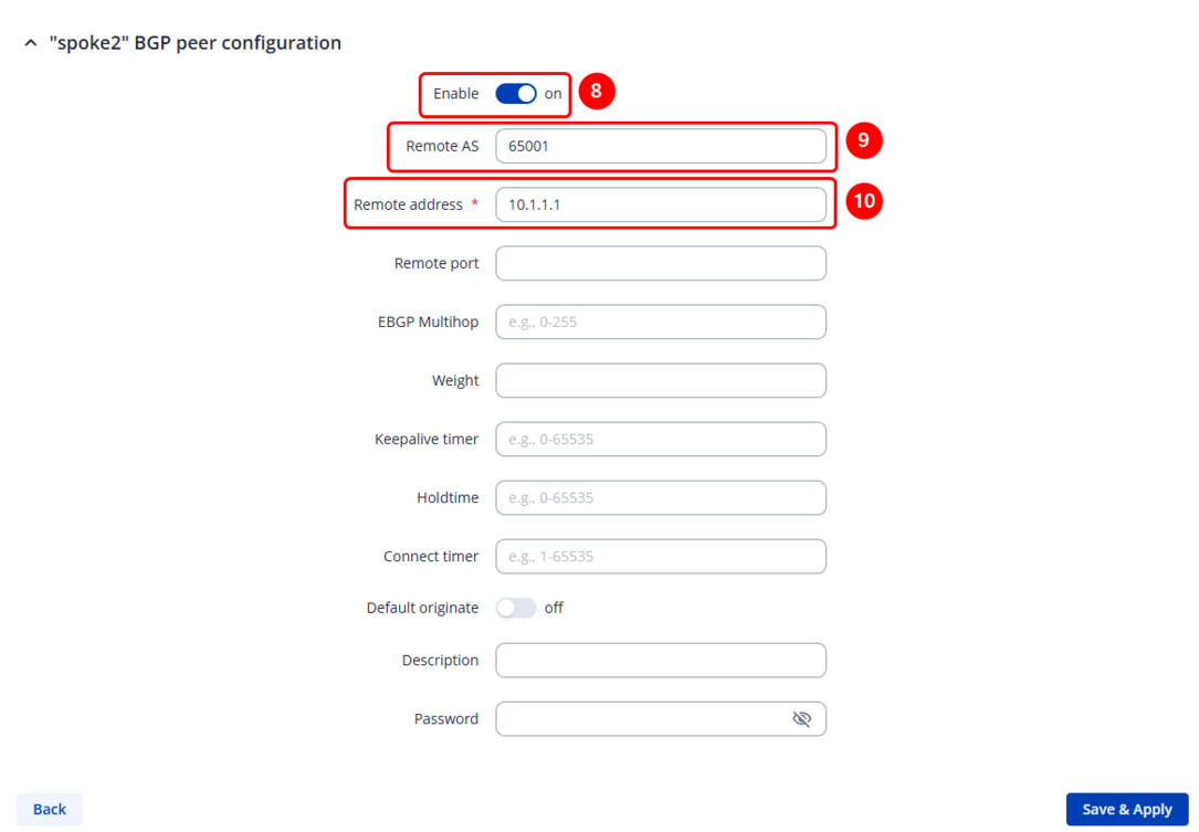
- Write the Name of the new BGP peer instance (anything you want).
- Press the Add button, and then the new BGP peer configuration window will appear.

- Inside the BGP peer configuration window, enable the instance
- Set Remote AS (should match previously set AS)
- Set the remote address (either of the other spoke or the hub internal DMVPN IPs)
- Once saved and applied, the changes should be reflected in the BGP peers configuration section.
- Write the Name of the new BGP peer group instance (anything you want).
- Press the Add button, and then the new BGP peer group configuration window will appear.
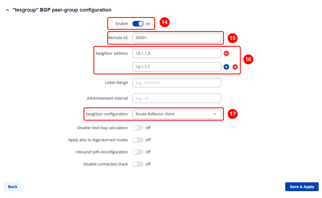
- Inside the BGP peer group configuration window, enable the instance.
- Set Remote AS (should match previously set AS)
- Set the neighbor addresses – they should be the other spokes and your hubs' internal DMVPN IPs.
- Set Neighbor configuration to Route Reflector Client.
- Once saved and applied, some changes should be seen in BGP peer groups section.
- Save the configuration.


STEP 5: Configure forwarding between GRE and LAN zones.
Go to network -> Firewall -> Zones and modify gre => lan zone’s Forwarding inside zone to Accept. Then save & apply.

Repeat this on different routers as many times as the number of Spokes that you need. Remember that other Spokes will have different LAN, WAN and GRE IP addresses.
HUB configuration
This section contains information on how to configure DMVPN HUB.
STEP 1: Connect to router's WebUI, go to Services > VPN > DMVPN. Enter a name for your DMVPN instance, click ADD and when instance appears in DMVPN CONFIGURATION field, click Edit.

STEP 2: Configure DMVPN settings.

- Enable instance.
- Select Working mode (HUB).
- Select Tunnel source (select your WAN interface).
- Write Local GRE interface IP address (create GRE tunnel IP address or just use the same as in the example).
- Write Local GRE interface netmask.
- Add GRE MTU (largest PDU size of any single transaction).
- (optional) Write Inbound and outbound keys (hub keys should be mirrored from the spokes – outbound becomes inbound and et cetera).
- Add Pre-shared key (it must match with the Spokes).
- (optional) Write IKE lifetime (how long the keying channel of a connection should last before being renegotiated). Do this in PHASE 1 and PHASE 2. They should match on spokes too.
- Leave everything else as default and click Save & Apply.
STEP 3: Go to Network > Routing > Dynamic Routes > BGP, enable BGP and vty, and either create a new BGP instance or modify the default “general” instance:
STEP 4: Configure BGP instance settings:

- Enable instance.
- Add AS (Autonomous system name, it must match on all of the devices).
- Write BGP router ID (HUB GRE Tunnel IP).
- Add Network (HUB LAN network IP with subnet mask).
- Select Redistribution options. (NHRP routes)
- Repeat steps 6 to 10 for each of the other spokes.
- Write the Name of the new BGP peer instance (anything you want).
- Press the Add button, and then the new BGP peer configuration window will appear.
- Inside the BGP peer configuration window, enable the instance
- Set Remote AS (should match previously set AS)
- Set the remote address (selected spokes IP)
- Once saved and applied, the changes should be reflected in the BGP peers configuration section.
- Write the Name of the new BGP peer group instance (anything you want).
- Press the Add button, and then the new BGP peer group configuration window will appear.

- Inside the BGP peer group configuration window, enable the instance.
- Set Remote AS (should match previously set AS)
- Set the neighbor addresses – they should be spokes internal DMVPN IPs.
- Set Neighbor configuration to Route Reflector Client.
- Once saved and applied, some changes should be seen in BGP peer groups section.
- Save the configuration.

STEP 5: Configure forwarding between GRE and LAN zones.
Go to network -> Firewall -> Zones and modify gre => lan zone’s Forwarding inside zone to Accept. Then save & apply.
Testing configuration
Please keep in mind that network propagation only occurs when another device is connected to the router (for example, via LAN).
The only exception is the RUTXxx series, which always shares its network information with other spokes and hubs automatically.
When testing, make sure that all routers have at least one client device connected to ensure proper network propagation throughout the DMVPN network.
Access HUB or either of the Spokes WebUI, go to Status -> Routes -> Dynamic, and check if there are routes to other device networks:
SPOKE example:

HUB example:

Another way to test the configuration is to connect to one of the devices over SSH or CLI and check the available routes using ip r command:
Available routes on HUB:

Available routes on spoke:
