|
|
| Line 7: |
Line 7: |
| | [[File:Rut955 power led v3.png|300px]] | | [[File:Rut955 power led v3.png|300px]] |
| | | | |
| − | It can only perform two different actions:
| + | {{Template: rut_power_led_table}} |
| − | | |
| − | {| class="wikitable" | |
| − | |+
| |
| − | ! style="width: 500px; border: 1px solid white; border-bottom: 2px solid #0054A6; background: white; color: #0054A6; text-align: left;" | ACTION
| |
| − | ! style="width: 300px; border: 1px solid white; border-bottom: 2px solid #0054A6; background: white; color: #0054A6; text-align: left;" | DESCRIPTION
| |
| − | |-
| |
| − | ! style="border: 1px solid white; border-bottom: 2px solid #E8E8E8; text-align: left; vertical-align: top; background: white;" | LED turned ON
| |
| − | | style="border: 1px solid white; border-bottom: 2px solid #E8E8E8; text-align: left; vertical-align: top; background: white;" | Router is powered up
| |
| − | |-
| |
| − | ! style="border: 1px solid white; border-bottom: 2px solid #E8E8E8; text-align: left; vertical-align: top; background: white;" | LED turned OFF
| |
| − | | style="border: 1px solid white; border-bottom: 2px solid #E8E8E8; text-align: left; vertical-align: top; background: white;" | Router is not powered up
| |
| − | |-
| |
| − | |}
| |
| | | | |
| | ==Ethernet port LEDs== | | ==Ethernet port LEDs== |
| Line 28: |
Line 15: |
| | [[File:Rut955 ethernet port leds v3.png|300px]] | | [[File:Rut955 ethernet port leds v3.png|300px]] |
| | | | |
| − | They represent activity happening on the router's Ethernet ports:
| + | {{Template: rut_ethernet_port_led_table}} |
| − | | |
| − | {| class="wikitable" | |
| − | |+
| |
| − | ! style="width: 500px; border: 1px solid white; border-bottom: 2px solid #0054A6; background: white; color: #0054A6; text-align: left;" | ACTION
| |
| − | ! style="width: 300px; border: 1px solid white; border-bottom: 2px solid #0054A6; background: white; color: #0054A6; text-align: left;" | DESCRIPTION
| |
| − | |-
| |
| − | ! style="border: 1px solid white; border-bottom: 2px solid #E8E8E8; text-align: left; vertical-align: top; background: white;" | LED turned ON
| |
| − | | style="border: 1px solid white; border-bottom: 2px solid #E8E8E8; text-align: left; vertical-align: top; background: white;" | Operating as a 10/100 Mbps connection
| |
| − | |-
| |
| − | ! style="border: 1px solid white; border-bottom: 2px solid #E8E8E8; text-align: left; vertical-align: top; background: white;" | LED turned OFF
| |
| − | | style="border: 1px solid white; border-bottom: 2px solid #E8E8E8; text-align: left; vertical-align: top; background: white;" | No link established
| |
| − | |-
| |
| − | ! style="border: 1px solid white; border-bottom: 2px solid #E8E8E8; text-align: left; vertical-align: top; background: white;" | LED blinking
| |
| − | | style="border: 1px solid white; border-bottom: 2px solid #E8E8E8; text-align: left; vertical-align: top; background: white;" | Connection established and there is activity on this port (data being transferred)
| |
| − | |-
| |
| − | |}
| |
| | | | |
| | ==Connection status LED== | | ==Connection status LED== |
| Line 52: |
Line 23: |
| | [[File:Rut955 connection status led v3.png|300px]] | | [[File:Rut955 connection status led v3.png|300px]] |
| | | | |
| − | The LEDs display the router's current connection state and network type among a few other things:
| + | {{Template: rut_connection_status_led_table}} |
| − | | |
| − | {| class="wikitable" | |
| − | |+
| |
| − | ! style="width: 500px; border: 1px solid white; border-bottom: 2px solid #0054A6; background: white; color: #0054A6; text-align: left;" | ACTION
| |
| − | ! style="width: 300px; border: 1px solid white; border-bottom: 2px solid #0054A6; background: white; color: #0054A6; text-align: left;" | DESCRIPTION
| |
| − | |-
| |
| − | ! style="border: 1px solid white; border-bottom: 2px solid #E8E8E8; text-align: left; vertical-align: top; background: white;" | <span style="color: green>'''Green'''</span> and <span style="color: red>'''red'''</span> blinking alternatively ever 500 ms
| |
| − | | style="border: 1px solid white; border-bottom: 2px solid #E8E8E8; text-align: left; vertical-align: top; background: white;" | No SIM or bad PIN
| |
| − | |-
| |
| − | ! style="border: 1px solid white; border-bottom: 2px solid #E8E8E8; text-align: left; vertical-align: top; background: white;" | <span style="color: green>'''Green'''</span>, <span style="color: red>'''red'''</span> and <span style="color: #F0DE00">'''yellow'''</span> blinking alternatively every 500 ms
| |
| − | | style="border: 1px solid white; border-bottom: 2px solid #E8E8E8; text-align: left; vertical-align: top; background: white;" | Connecting to GSM
| |
| − | |-
| |
| − | ! style="border: 1px solid white; border-bottom: 2px solid #E8E8E8; text-align: left; vertical-align: top; background: white;" | <span style="color: red>'''Red'''</span> blinking every 1 sec
| |
| − | | style="border: 1px solid white; border-bottom: 2px solid #E8E8E8; text-align: left; vertical-align: top; background: white;" | Connected 2G, no data session established
| |
| − | |-
| |
| − | ! style="border: 1px solid white; border-bottom: 2px solid #E8E8E8; text-align: left; vertical-align: top; background: white;" | <span style="color: #F0DE00">'''Yellow'''</span> blinking every 1 sec
| |
| − | | style="border: 1px solid white; border-bottom: 2px solid #E8E8E8; text-align: left; vertical-align: top; background: white;" | Connected 3G, no data session established
| |
| − | |-
| |
| − | ! style="border: 1px solid white; border-bottom: 2px solid #E8E8E8; text-align: left; vertical-align: top; background: white;" | <span style="color: green>'''Green'''</span> blinking every 1 sec
| |
| − | | style="border: 1px solid white; border-bottom: 2px solid #E8E8E8; text-align: left; vertical-align: top; background: white;" | Connected 4G, no data session established
| |
| − | |-
| |
| − | ! style="border: 1px solid white; border-bottom: 2px solid #E8E8E8; text-align: left; vertical-align: top; background: white;" | <span style="color: red>'''Red'''</span> lit and blinking rapidly while data is being transferred
| |
| − | | style="border: 1px solid white; border-bottom: 2px solid #E8E8E8; text-align: left; vertical-align: top; background: white;" | Connected 2G with data session
| |
| − | |-
| |
| − | ! style="border: 1px solid white; border-bottom: 2px solid #E8E8E8; text-align: left; vertical-align: top; background: white;" | <span style="color: #F0DE00">'''Yellow'''</span> lit and blinking rapidly while data is being transferred
| |
| − | | style="border: 1px solid white; border-bottom: 2px solid #E8E8E8; text-align: left; vertical-align: top; background: white;" | Connected 3G with data session
| |
| − | |-
| |
| − | ! style="border: 1px solid white; border-bottom: 2px solid #E8E8E8; text-align: left; vertical-align: top; background: white;" | <span style="color: green>'''Green'''</span> lit and blinking rapidly while data is being transferred
| |
| − | | style="border: 1px solid white; border-bottom: 2px solid #E8E8E8; text-align: left; vertical-align: top; background: white;" | Connected 4G with data session
| |
| − | |-
| |
| − | |}
| |
| | | | |
| | ==Signal strength LEDs== | | ==Signal strength LEDs== |
| Line 90: |
Line 30: |
| | | | |
| | [[File:Rut955 signal strength leds v3.png|300px]] | | [[File:Rut955 signal strength leds v3.png|300px]] |
| − |
| |
| − | Each lit up LED represents a different value of the router's current signal strength in [[RSSI]]:
| |
| | | | |
| | {{signal strength leds table}} | | {{signal strength leds table}} |
This chapter provides explanations for LED actions on a RUT955 router.
Power LED
The power LED is located on the bottom left corner of the front panel, just under the power connector:
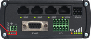
It can perform two different actions:
| ACTION
|
DESCRIPTION
|
| LED turned ON
|
Router is powered up
|
| LED turned OFF
|
Router is not powered up
|
Ethernet port LEDs
The Ethernet port LEDs are located on the router's front panel, under each respective Ethernet port:
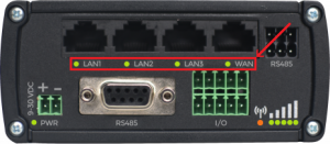
They represent activity happening on the router's Ethernet ports:
| ACTION
|
DESCRIPTION
|
| LED turned ON
|
Operating as a 10/100 Mbps connection
|
| LED turned OFF
|
No link established
|
| LED blinking
|
Connection established and there is activity on this port (data being transferred)
|
| LEDs light up and turn OFF in sequence from WAN port to LAN1 port
|
The router is in the bootloader menu state*
|
Connection status LED
The connection status LED is located on the bottom right corner of the front panel, between the input/output connector and signal strength indication LEDs:
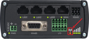
Template:Rut connection status led table
Signal strength LEDs
The signal strength LEDs are located on the bottom right corner of the front panel, to the right of the connection status LED:
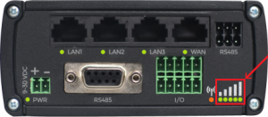
Each lit up LED represents a different value of the router's current signal strength in RSSI:
| NO. OF LIT UP LEDs
|
SIGNAL STRENGTH VALUE
|
| 0
|
≤ -111 dBm
|
| 1
|
-110 dBm to -97 dBm
|
| 2
|
-96 dBm to -82 dBm
|
| 3
|
-81 dBm to -67 dBm
|
| 4
|
-66 dBm to -52 dBm
|
| 5
|
≥ -51 dBm
|
The signal strength LEDs can also be used as a time indicator for holding the reset button. When you press and hold the reset button, if there is a User's default configuration configured on the device, you have to hold it pressed for 6 seconds (by default) to initiate a User's default configuration reset and 12 seconds (by default) to initiate a Factory reset. Otherwise, it is only necessary to hold the reset button for 6 seconds to trigger a Factory reset. If the button was held down longer than 20 seconds (by default) no action will be taken.
While holding the reset button each lit up signal strength LED indicate that a period of two seconds has passed. When all 5 signal strength LEDs are lit up, they represent that 10 (LED number multiplied by 2) seconds have passed since you pressed down on the reset button.
After releasing the button at one of the reset periods, all 5 LEDs will start blinking every 1 second. This signifies that the router has begun the reset.


