|
|
| (29 intermediate revisions by 5 users not shown) |
| Line 1: |
Line 1: |
| − | ==Summary==
| + | {{Template: Networking_rutos_manual_rs232 |
| − | | + | <!------------------------DEVICE-----------------------> |
| − | RS232 and RS485 functions are designed to utilize available serial interfaces of the router. Serial interfaces provide a possibility for legacy devices to gain access to IP networks. This chapter is an overview of the RS232/RS485 functions in RUT routers.
| + | | name = RUT955 |
| − | | + | | series = RUT9 |
| − | ==RS232==
| + | <!----------------------SEPARATORS---------------------> |
| − | | + | | baud_rate = 115200 <!-- Default baud rate --> |
| − | [[File:Services rs232 v 2.png]]
| + | | baud_rates = 300 {{!}} 600 {{!}} 1200 {{!}} 2400 {{!}} 4800 {{!}} 9600 {{!}} 19200 {{!}} 38400 {{!}} 57600 {{!}} 115200 <!-- All baud rate values--> |
| − | | + | | data_bit = 8 <!-- Default data bits --> |
| − | <table class="nd-mantable"> | + | | data_bits = 5 {{!}} 6 {{!}} 7 {{!}} 8 <!-- All data bits values --> |
| − | <tr>
| + | | modem = 1 |
| − | <th>field name</th>
| + | }} |
| − | <th>value</th>
| |
| − | <th>description</th>
| |
| − | </tr>
| |
| − | <tr>
| |
| − | <td>Enabled</td>
| |
| − | <td>yes | no; Default: '''no'''</td>
| |
| − | <td>When checked, enables the RS232 service</td>
| |
| − | </tr>
| |
| − | <tr>
| |
| − | <td>Baud rate</td>
| |
| − | <td>300 | 1200 | 2400 | 4800 | 9600 | 19200 | 38400 | 57600 | 115200; Default: '''115200'''</td>
| |
| − | <td>Sets the data rate for serial data transmission (in bits per second)</td>
| |
| − | </tr>
| |
| − | <tr>
| |
| − | <td>Data bits</td>
| |
| − | <td>5 | 6 | 7 | 8; Default: '''8'''</td>
| |
| − | <td>The number of data bits for each character</td>
| |
| − | </tr>
| |
| − | <tr>
| |
| − | <td>Parity</td>
| |
| − | <td>None | Odd | Even; Default: '''None'''</td>
| |
| − | <td>In serial transmission, parity is a method of detecting errors. An extra data bit is sent with each data character, arranged so that the number of 1 bits in each character, including the parity bit, is always odd or always even. If a byte is received with the wrong number of 1s, then it must have been corrupted. However, an even number of errors can pass the parity check. <br> '''None''' ('''N''') - no parity method is used <br> '''Odd''' ('''O''') - the parity bit is set so that the number of "logical ones (1s)" has to be odd <br> '''Even''' ('''E''') - the parity bit is set so that the number of "logical ones (1s)" has to be even</td>
| |
| − | </tr>
| |
| − | <tr>
| |
| − | <td>Stop bits</td>
| |
| − | <td>1 | 2; Default: '''1'''</td>
| |
| − | <td>Stop bits sent at the end of every character allow the receiving signal hardware to detect the end of a character and to resynchronise with the character stream. Electronic devices usually use one stop bit. Two stop bits are required if slow electromechanical devices are used</td>
| |
| − | </tr>
| |
| − | <tr>
| |
| − | <td>Flow control</td>
| |
| − | <td>None | RTS/CTS | Xon/Xoff; Default: '''None'''</td>
| |
| − | <td>In many circumstances a transmitter might be able to send data faster than the receiver is able to process it. To cope with this, serial lines often incorporate a "handshaking" method, usually distinguished between hardware and software handshaking. <br> '''RTS/CTS''' - hardware handshaking. RTS and CTS are turned OFF and ON from alternate ends to control data flow, for instance when a buffer is almost full <br> '''Xon/Xoff''' - software handshaking. The Xon and Xoff characters are sent by the receiver to the sender to control when the sender will send data, i.e., these characters go in the opposite direction to the data being sent. The circuit starts in the "sending allowed" state. When the receiver's buffers approach capacity, the receiver sends the Xoff character to tell the sender to stop sending data. Later, after the receiver has emptied its buffers, it sends an Xon character to tell the sender to resume transmission</td>
| |
| − | </tr>
| |
| − | <tr>
| |
| − | <td>Serial type</td>
| |
| − | <td>[[RUT955_RS232/RS485#Console|Console]] | [[RUT955_RS232/RS485#Over_IP|Over IP]] | [[RUT955_RS232/RS485#Modem|Modem]] | [[RUT955_RS232/RS485#Modbus_gateway|Modbus gateway]] | [[RUT955_RS232/RS485#NTRIP_client|NTRIP client]]; Default: <b>Console</b></td>
| |
| − | <td>Specifies the serial connection type.</td>
| |
| − | </tr>
| |
| − | <tr>
| |
| − | <td>Echo</td>
| |
| − | <td>yes | no; Default: '''no'''</td>
| |
| − | <td>Toggles RS232 echo ON or OFF. RS232 echo is a loopback test usually used to check whether the RS232 cable is working properly</td>
| |
| − | </tr>
| |
| − | </table>
| |
| − | | |
| − | ===RS232 Connector Pinout===
| |
| − | ---- | |
| − | RS232 connector type on this device is DCE female. DCE stands for Data Communication Equipment.
| |
| − | | |
| − | [[Image:Services rs232 connector.PNG]]
| |
| − | | |
| − | <table class="nd-othertables">
| |
| − | <tr>
| |
| − | <th style="width: 30px">PIN</th>
| |
| − | <th style="width: 60px">NAME*</th>
| |
| − | <th style="width: 170px">DESCRIPTION*</th>
| |
| − | <th style="width: 400px">DIRECTION ON THIS DEVICE</th>
| |
| − | </tr>
| |
| − | <tr>
| |
| − | <td>1</td>
| |
| − | <td>DCD</td>
| |
| − | <td>Data Carrier Detect</td>
| |
| − | <td>Output</td>
| |
| − | </tr>
| |
| − | <tr>
| |
| − | <td>2</td>
| |
| − | <td>RXD</td>
| |
| − | <td>Receive Data</td>
| |
| − | <td>Output</td>
| |
| − | </tr>
| |
| − | <tr>
| |
| − | <td>3</td>
| |
| − | <td>TXD</td>
| |
| − | <td>Transmit Data</td>
| |
| − | <td>Input</td>
| |
| − | </tr>
| |
| − | <tr>
| |
| − | <td>4</td>
| |
| − | <td>DTR</td>
| |
| − | <td>Data Terminal Ready</td>
| |
| − | <td>Input</td>
| |
| − | </tr>
| |
| − | <tr>
| |
| − | <td>5</td>
| |
| − | <td>GND</td>
| |
| − | <td>Signal Ground</td>
| |
| − | <td>-</td>
| |
| − | </tr>
| |
| − | <tr>
| |
| − | <td>6</td>
| |
| − | <td>DSR</td>
| |
| − | <td>Data Set Ready</td>
| |
| − | <td>Output</td>
| |
| − | </tr>
| |
| − | <tr>
| |
| − | <td>7</td>
| |
| − | <td>RTS</td>
| |
| − | <td>Ready To Send</td>
| |
| − | <td>Input</td>
| |
| − | </tr>
| |
| − | <tr>
| |
| − | <td>8</td>
| |
| − | <td>CTS</td>
| |
| − | <td>Clear To Send</td>
| |
| − | <td>Output</td>
| |
| − | </tr>
| |
| − | <tr>
| |
| − | <td>9</td>
| |
| − | <td>RI</td>
| |
| − | <td>Ring Indicator</td>
| |
| − | <td>Output (connected to +5V permanently via a 4.7k resistor) </td>
| |
| − | </tr>
| |
| − | </table>
| |
| − | | |
| − | '''*''' The names and descriptions that indicate signal direction (such as TXD, RXD, RTS, CTS, DTR, and DSR) are named from the point of view of the DTE device.
| |
| − | | |
| − | ===Cables===
| |
| − | ---- | |
| − | {{Template: webui_services_rs232_cables}}
| |
| − | | |
| − | ==RS485==
| |
| − | | |
| − | '''RS-485''' is a different serial data transmission standard for use in long ranges or noisy environments.
| |
| − | | |
| − | [[Image:Services rs485.PNG]]
| |
| − | | |
| − | <table class="nd-mantable">
| |
| − | <tr>
| |
| − | <th>field name</th>
| |
| − | <th>value</th>
| |
| − | <th>description</th>
| |
| − | </tr>
| |
| − | <tr>
| |
| − | <td>Enabled</td>
| |
| − | <td>yes | no; Default: '''no'''</td>
| |
| − | <td>Toggles the RS485 serial port function ON or OFF</td>
| |
| − | </tr>
| |
| − | <tr>
| |
| − | <td>Baud rate</td>
| |
| − | <td>300 | 1200 | 2400 | 4800 | 9600 | 19200 | 38400 | 57600 | 115200; Default: '''115200'''</td>
| |
| − | <td>The communication speed of the serial interface</td>
| |
| − | </tr>
| |
| − | <tr>
| |
| − | <td>Parity</td>
| |
| − | <td>None | Odd | Even; Default: '''None'''</td>
| |
| − | <td>The parity bit setting used for error detection during data transfer</td>
| |
| − | </tr>
| |
| − | <tr>
| |
| − | <td>Flow control</td>
| |
| − | <td>None | RTS- CTS | Xon-Xoff; Default: '''None'''</td>
| |
| − | <td>Specifies how many stop bits will be used to detect the end of character</td>
| |
| − | </tr>
| |
| − | <tr>
| |
| − | <td>Serial type</td>
| |
| − | <td>Console | Over IP | Modem | Modbus Gateway | NTRIP Client; Default: '''Console'''</td>
| |
| − | <td>Specifies the function of the serial interface</td>
| |
| − | </tr>
| |
| − | <tr>
| |
| − | <td>Interface</td>
| |
| − | <td>LAN | WAN | VPN | L2TP | PPTP | GRE | HOTSPOT | SSTP; Default: '''LAN'''</td>
| |
| − | <td>Interface used for connection</td>
| |
| − | </tr>
| |
| − | <tr>
| |
| − | <td>Allow IP</td>
| |
| − | <td>ip; Default: " "</td>
| |
| − | <td>Allows IP to connect to server</td>
| |
| − | </tr>
| |
| − | </table>
| |
| − | | |
| − | ===Maximum data rate vs. transmission line length===
| |
| − | ---- | |
| − | RS-485 standart can be used for network lengths up to 1200 meters, but the maximum usable data rate decreases as the transmission length increases. A device operating at the maximum data transfer rate (10Mbps) is limited to a transmission length of about 12 meters, while the 100kbps data rate can achieve a distance up to 1200 meters. A rough relation between maximum transmission length and data rate can be calculated using this approximation:
| |
| − | | |
| − | [[Image:Services rs485 formula.PNG]]
| |
| − | | |
| − | Where Lmax is the maximum transmission length in meters and DR is maximum data rate in bits per second.
| |
| − | | |
| − | Twisted pair is the prefered cable type for RS-485 networks. Twisted pair cables pick up noise and other electromagnetically induced voltages as common mode signals, which are rejected by the differential receivers.
| |
| − | | |
| − | ===Cable Type===
| |
| − | ---- | |
| − | Recommended cable parameters:
| |
| − | | |
| − | <table class="nd-othertables">
| |
| − | <tr>
| |
| − | <th style="width: 300px">PARAMETER</th>
| |
| − | <th style="width: 350px">VALUE</th>
| |
| − | </tr>
| |
| − | <tr>
| |
| − | <td>Cable Type</td>
| |
| − | <td>22-24 AWG, 2 – pair (used for full-duplex networks ) or 1-pair (used for half duplex networks). One addtitional wire for ground connection is needed</td>
| |
| − | </tr>
| |
| − | <tr>
| |
| − | <td>Characteristic cable Impedance</td>
| |
| − | <td>120 Ω @ 1MHz</td>
| |
| − | </tr>
| |
| − | <tr>
| |
| − | <td>Capacitance (conductor to conductor)</td>
| |
| − | <td>36 pF/m</td>
| |
| − | </tr>
| |
| − | <tr>
| |
| − | <td>Propagation Velocity</td>
| |
| − | <td>78% (1.3 ns/ft)</td>
| |
| − | </tr>
| |
| − | </table>
| |
| − | | |
| − | ===RS485 connector pin-out===
| |
| − | ---- | |
| − | [[Image:Services rs485 port.PNG]]
| |
| − | | |
| − | <table class="nd-othertables">
| |
| − | <tr>
| |
| − | <th style="width: 65px">NAME</th>
| |
| − | <th style="width: 200px">DESCRIPTION</th>
| |
| − | <th style="width: 170px">TYPE</th>
| |
| − | </tr>
| |
| − | <tr>
| |
| − | <td>D_P</td>
| |
| − | <td>Driver positive signal</td>
| |
| − | <td>Differential Output</td>
| |
| − | </tr>
| |
| − | <tr>
| |
| − | <td>D_N</td>
| |
| − | <td>Driver negative signal</td>
| |
| − | <td>Differential Output</td>
| |
| − | </tr>
| |
| − | <tr>
| |
| − | <td>R_P</td>
| |
| − | <td>Receiver positive signal</td>
| |
| − | <td>Differential Input</td>
| |
| − | </tr>
| |
| − | <tr>
| |
| − | <td>R_N</td>
| |
| − | <td>Receiver negative signal</td>
| |
| − | <td>Differential Input</td>
| |
| − | </tr>
| |
| − | <tr>
| |
| − | <td>Ground</td>
| |
| − | <td>Device ground</td>
| |
| − | <td>Differential Output</td>
| |
| − | </tr>
| |
| − | </table>
| |
| − | | |
| − | ===2-Wire and 4-Wire Networks===
| |
| − | ---- | |
| − | Below is an example of a 4-wire network electrical connection. There are 3 devices shown in the example. One of the devices is the “master” and other two are “slaves”. Termination resistors are placed at each cable end. Four-wire networks consists of one „master“ with its transmitter connected to each of the “slaves‘” receivers on one twisted pair. The “slave” transmitters are all connected to the “master” receiver on a second twisted pair.
| |
| − | | |
| − | [[Image:Services rs485 4wire.PNG]]
| |
| − | | |
| − | Example 2-wire network electrical connection: to enable a 2-wire RS-485 configuration on a Teltonika router, you need to connect D_P to R_P and D_N to R_N on the device’s RS-485 socket. Termination resistors are placed at each
| |
| − | cable end.
| |
| − | | |
| − | [[Image:Services rs485 2wire.PNG]]
| |
| − | | |
| − | ===Termination===
| |
| − | ---- | |
| − | '''When to use (place jumper)'''
| |
| − | | |
| − | Termination resistor, equal in resistance to cable characteristic impedance, must be connected at each end of the cable to reduce reflection and ringing of the signals when the cable lengths get relatively long. Rise time of the RUT955 RS-485 driver is about 5 ns, so the maximum unterminated cable length is about 12 cm. As transmission line cables will always be longer than 12 cm, termination is mandatory all the time if RUT955 is located at the end of the cable.
| |
| − | | |
| − | '''When not to use (remove jumper)'''
| |
| − | | |
| − | If your RS-485 consists of more than two devices and the RUT955 router is located not on the end of the line but, for example, in the middle, RUT955 termination resistor needs to be disabled. In this case, place termination at other devices which are situated at the ends of the line.
| |
| − | | |
| − | '''How to enable termination'''
| |
| − | | |
| − | 120 Ω termination resistor is included on the RUT955 PCB and can be enabled by shorting contacts (shown in the picture below), placing 2.54mm pitch jumper:
| |
| − | | |
| − | [[Image:Services rs485 jumper.PNG]]
| |
| − | | |
| − | ===Number of devices in an RS-485 Network===
| |
| − | ---- | |
| − | One RUT955 RS-485 driver is capable of driving a maximum of 32 receivers, provided that the receiver input impedance is 12 kΩ. If receiver impedances are higher, the maximum number of receivers in the network increases. Any combination of receiver types can be connected together, provided their parallel impedance does not exceed RLoad > 375 Ω.
| |
| − | | |
| − | ==Modes of different serial types in RS232 and RS485==
| |
| − | | |
| − | ===Console===
| |
| − | ---- | |
| − | In this mode the serial interface set up as a Linux console of the device. It can be used for debugging purposes, to get the status of the device or to control it.
| |
| − | | |
| − | ===Over IP===
| |
| − | ---- | |
| − | In '''Over IP Serial''' type the router provides a connection to a TPC/IP network for the devices connected via serial interfaces.
| |
| − | | |
| − | ====Mode: Server====
| |
| − | ---- | |
| − | [[Image:Services rs232 rs485 overip server.PNG]]
| |
| − | | |
| − | <table class="nd-mantable">
| |
| − | <tr>
| |
| − | <th>field name</th>
| |
| − | <th>value</th>
| |
| − | <th>description</th>
| |
| − | </tr>
| |
| − | <tr>
| |
| − | <td>Protocol</td>
| |
| − | <td>TCP; Default: '''TCP'''</td>
| |
| − | <td>Specifies the protocol used in the communication process</td>
| |
| − | </tr>
| |
| − | <tr>
| |
| − | <td>Mode</td>
| |
| − | <td>Server | Client | Bidirect; Default: '''Server'''</td>
| |
| − | <td>Specifies the device's role in the connection: <br> '''Server''' - the device waits for incoming connections <br> '''Client''' - the device initiates the connection <br> '''Bidirect''' - acts as client by default but waits for incoming connections at the same time</td>
| |
| − | </tr>
| |
| − | <tr>
| |
| − | <td>No leading zeros</td>
| |
| − | <td>yes | no; Default: '''no'''</td>
| |
| − | <td>Specifies that the first hex zeros should be skipped</td>
| |
| − | </tr>
| |
| − | <tr>
| |
| − | <td>TCP port</td>
| |
| − | <td>integer [0..65535]; Default: " "</td>
| |
| − | <td>The port number used to connect to the server</td>
| |
| − | </tr>
| |
| − | <tr>
| |
| − | <td>Timeout (s)</td>
| |
| − | <td>integer; Default: " " </td>
| |
| − | <td>Disconnects clients after the amount of inactivity time (in seconds) specified in this field</td>
| |
| − | </tr>
| |
| − | </table>
| |
| − | | |
| − | ====Mode: Client====
| |
| − | ---- | |
| − | [[Image:Services rs232 rs485 overip client.PNG]]
| |
| − | | |
| − | <table class="nd-mantable">
| |
| − | <tr>
| |
| − | <th>field name</th>
| |
| − | <th>value</th>
| |
| − | <th>description</th>
| |
| − | </tr>
| |
| − | <tr>
| |
| − | <td>Protocol</td>
| |
| − | <td>TCP; Default: '''TCP'''</td>
| |
| − | <td>The protocol used for data transmission</td>
| |
| − | </tr>
| |
| − | <tr>
| |
| − | <td>Mode</td>
| |
| − | <td>Server | Client | Bidirect; Default: '''Server'''</td>
| |
| − | <td>'''Server''' - waits for incoming connection
| |
| − | | |
| − | '''Client''' - initiates the connection
| |
| − | | |
| − | '''Bidirect''' – acts as a client by default, but at the same time waits for incoming connections</td>
| |
| − | </tr>
| |
| − | <tr>
| |
| − | <td>No leading zeros</td>
| |
| − | <td>yes | no; Default: '''no'''</td>
| |
| − | <td>Skips first hex zeros</td>
| |
| − | </tr>
| |
| − | <tr>
| |
| − | <td>Server address</td>
| |
| − | <td>host | ip; Default: '''no'''</td>
| |
| − | <td>Server address to which the client will connect to</td>
| |
| − | </tr>
| |
| − | <tr>
| |
| − | <td>TCP port</td>
| |
| − | <td>integer [0..65535]; Default: " "</td>
| |
| − | <td>The port number used to listen for incoming connections</td>
| |
| − | </tr>
| |
| − | <tr>
| |
| − | <td>Reconnect intervals (s)</td>
| |
| − | <td>integer; Default: " "</td>
| |
| − | <td>Indicates the time period between reconnection attempts</td>
| |
| − | </tr>
| |
| − | </table>
| |
| − | | |
| − | ====Mode: Bidirect====
| |
| − | ---- | |
| − | [[Image:Services_rs232_rs485_overip_bidirect.PNG]]
| |
| − | | |
| − | <table class="nd-mantable">
| |
| − | <tr>
| |
| − | <th>field name</th>
| |
| − | <th>value</th>
| |
| − | <th>description</th>
| |
| − | </tr>
| |
| − | <tr>
| |
| − | <td>Mode</td>
| |
| − | <td>Server | Client | Bidirect; Default: '''Server'''</td>
| |
| − | <td>'''Server''' - waits for incoming connection
| |
| − | | |
| − | '''Client''' - initiates the connection
| |
| − | | |
| − | '''Bidirect''' – acts as a client by default, but at the same time waits for incoming connections</td>
| |
| − | </tr>
| |
| − | <tr>
| |
| − | <td>No leading zeros </td>
| |
| − | <td>yes | no; Default: '''no'''</td>
| |
| − | <td>Skips first hex zeros</td>
| |
| − | </tr>
| |
| − | <tr>
| |
| − | <td>Server address</td>
| |
| − | <td>host | ip; Default: '''no'''</td>
| |
| − | <td>Server address to which the client will connect to</td>
| |
| − | </tr>
| |
| − | <tr>
| |
| − | <td>TCP port</td>
| |
| − | <td>integer [0..65535]; Default: " "</td>
| |
| − | <td>The port number used to listen for incoming connections</td>
| |
| − | </tr>
| |
| − | <tr>
| |
| − | <td>Reconnect intervals (s)</td>
| |
| − | <td>integer; Default: " "</td>
| |
| − | <td>Indicates the time period between reconnection attempts</td>
| |
| − | </tr>
| |
| − | <tr>
| |
| − | <td>TCP port</td>
| |
| − | <td>integer [0..65535]; Default: " "</td>
| |
| − | <td>The port number used to listen for incoming connections</td>
| |
| − | </tr>
| |
| − | <tr>
| |
| − | <td>Timeout (s)</td>
| |
| − | <td>integer; Default: " "</td>
| |
| − | <td>Disconnects client after the specified timeout of inactivity</td>
| |
| − | </tr>
| |
| − | <tr>
| |
| − | <td>Output</td>
| |
| − | <td>OC Output | Relay Output; Default: '''OC Output'''</td>
| |
| − | <td>Output to indicate that application switched from client (default) to server state</td>
| |
| − | </tr>
| |
| − | <tr>
| |
| − | <td>Output state</td>
| |
| − | <td>integer [0..1]; Default: '''0'''</td>
| |
| − | <td>Output state value after the application reverts to server mode</td>
| |
| − | </tr>
| |
| − | </table>
| |
| − | | |
| − | ===Modem===
| |
| − | ----
| |
| − | With Modem Serial type, the router imitates a dial-up modem. Connections to TCP/IP networks can be established using AT commands. The connection can be initiated by the device connected via serial interface with an ATD command: ATD <host>:<port>. If Direct connect settings are specified, the connection to the server is always active. Data mode can be entered by issuing the ATD command. Incoming connections are indicated by sending a RING to the serial interface.
| |
| − | | |
| − | [[File:Services rs232 rs485 modem v 2.png]]
| |
| − | | |
| − | <table class="nd-mantable">
| |
| − | <tr>
| |
| − | <th>field name</th>
| |
| − | <th>value</th>
| |
| − | <th>description</th>
| |
| − | </tr>
| |
| − | <tr>
| |
| − | <td>Direct connect</td>
| |
| − | <td>host:port | ip:port; Default: " "</td>
| |
| − | <td>Maintains a constant connection to specified host. Leave empty to use an ATD command to initiate the connection</td>
| |
| − | </tr>
| |
| − | <tr>
| |
| − | <td>TCP port</td>
| |
| − | <td>integer [0..65535]; Default: " "</td>
| |
| − | <td>The port number used to listen for incoming connections. Leave it empty to disable incoming connections</td>
| |
| − | </tr>
| |
| − | <tr>
| |
| − | <td>Initiation string</td>
| |
| − | <td>string; Default: " "</td>
| |
| − | <td>A command string that will be sent to the modem to initiate it in some special way</td>
| |
| − | </tr>
| |
| − | <tr>
| |
| − | <td>No extra CR LF in response</td>
| |
| − | <td>yes | no; Default: '''yes'''</td>
| |
| − | <td>Removes extra CR LF before and LF after response code</td>
| |
| − | </tr>
| |
| − | </table>
| |
| − | | |
| − | This is the AT command set<span class="asterisk">*</span> used in Modem mode of the serial interfaces:
| |
| − | | |
| − | <table class="nd-othertables">
| |
| − | <tr>
| |
| − | <th style="width: 85px">COMMAND</th>
| |
| − | <th style="width: 210px">DESCRIPTION</th>
| |
| − | <th style="width: 360px">USAGE</th>
| |
| − | </tr>
| |
| − | <tr>
| |
| − | <td>A</td>
| |
| − | <td>Answers incoming call</td>
| |
| − | <td>To answer incoming connection: ATA</td>
| |
| − | </tr>
| |
| − | <tr>
| |
| − | <td>D</td>
| |
| − | <td>Dial a number</td>
| |
| − | <td>To initiate data connection: ATD <host>:<port> <br>
| |
| − | | |
| − | To enter data mode with Direct connect settings: ATD</td>
| |
| − | </tr>
| |
| − | <tr>
| |
| − | <td>E</td>
| |
| − | <td>Local echo</td>
| |
| − | <td>Turn local echo on: ATE1<br>
| |
| − | | |
| − | Turn local echo off: ATE0</td>
| |
| − | </tr>
| |
| − | <tr>
| |
| − | <td>H</td>
| |
| − | <td>Hang up current call</td>
| |
| − | <td>To end data connection: ATH</td>
| |
| − | </tr>
| |
| − | <tr>
| |
| − | <td>O</td>
| |
| − | <td>Return to data mode</td>
| |
| − | <td>To return to data mode from command mode: ATO</td>
| |
| − | </tr>
| |
| − | <tr>
| |
| − | <td>Z</td>
| |
| − | <td>Reset to default configuration</td>
| |
| − | <td>To reset the modem to default configuration: ATZ</td>
| |
| − | </tr>
| |
| − | </table>
| |
| − | <font size="-1"><span class="asterisk">*</span> Only these commands are supported in Modem mode.</font>
| |
| − | | |
| − | ===Modbus gateway===
| |
| − | ---- | |
| − | The Modbus gateway Serial type allows redirecting TCP data coming to a specified port to RTU specified by the Slave ID. The Slave ID can be specified by the user or be obtained directly from the Modbus header.
| |
| − | | |
| − | [[Image:Services_rs232_rs485_modbus_gateway.PNG]]
| |
| − | | |
| − | <table class="nd-mantable">
| |
| − | <tr>
| |
| − | <th>field name</th>
| |
| − | <th>value</th>
| |
| − | <th>description</th>
| |
| − | </tr>
| |
| − | <tr>
| |
| − | <td>Listening IP</td>
| |
| − | <td>ip; Default: '''0.0.0.0'''</td>
| |
| − | <td>IP address on which the Modbus gateway will wait for incoming connections</td>
| |
| − | </tr>
| |
| − | <tr>
| |
| − | <td>Port</td>
| |
| − | <td>integer [0..65535]; Default: " "</td>
| |
| − | <td>The port number used to listen for incoming connections</td>
| |
| − | </tr>
| |
| − | <tr>
| |
| − | <td>Slave ID configuration type</td>
| |
| − | <td>User defined | Obtained from TCP; Default: '''User defined'''</td>
| |
| − | <td>Specifies whether slave IDs are user defined or automatically obtained from TCP</td>
| |
| − | </tr>
| |
| − | <tr>
| |
| − | <td>Slave ID | Permitted slave IDs</td>
| |
| − | <td>integer | range of integers; Default: '''1'''</td>
| |
| − | <td>Specifies the slave ID of range of permitted slave IDs. The way this field is named and its function depends on the value of the ''Slave ID configuration'' field. <br> A range of IDs can be specified by placing a '''hyphen''' ('''-''') between two integer numbers. For example, if you permitt slave IDs in the range of 10 to 20, you would specify it as: '''10-20''' <br> You can also specify multiple values that are not connected in a range using '''commas''' (''','''). For example, to specify 6, 50 and 100 as permitted slave IDs, you would have to use: '''6,50,100'''</td>
| |
| − | </tr>
| |
| − | </table>
| |
| − | | |
| − | ===NTRIP===
| |
| − | ----
| |
| − | Networked Transport of RTCM via Internet Protocol (Ntrip) is a protocol for streaming differential GPS (DGPS) data over the Internet in accordance with specification published by RTCM.
| |
| − | | |
| − | [[Image:Services rs232 rs485 ntrip.PNG]]
| |
| − | | |
| − | <table class="nd-mantable">
| |
| − | <tr>
| |
| − | <th>field name</th>
| |
| − | <th>value</th>
| |
| − | <th>description</th>
| |
| − | </tr>
| |
| − | <tr>
| |
| − | <td>IP address</td>
| |
| − | <td>ip; Default: '''0.0.0.0'''</td>
| |
| − | <td>IP address of the NTRIP server </td>
| |
| − | </tr>
| |
| − | <tr>
| |
| − | <td>Port</td>
| |
| − | <td>integer [0..65535]; Default: " "</td>
| |
| − | <td>TCP/UDP port used for NTRIP communication</td>
| |
| − | </tr>
| |
| − | <tr>
| |
| − | <td>Mount point</td>
| |
| − | <td>string; Default: " "</td>
| |
| − | <td>NTRIP mount point</td>
| |
| − | </tr>
| |
| − | <tr>
| |
| − | <td>Data format</td>
| |
| − | <td>NTRIP V2.0 TCP/IP | NTRIP V2.0 RSTP/RTP | NTRIP V1.0 | Automatic detection | NTRIP V2.0 UDP; Default: '''NTRIP V1.0'''</td>
| |
| − | <td>Specifies the used version of NTRIP </td>
| |
| − | </tr>
| |
| − | <tr>
| |
| − | <td>Username</td>
| |
| − | <td>string; Default: " "</td>
| |
| − | <td>User name for NTRIP authentication</td>
| |
| − | </tr>
| |
| − | <tr>
| |
| − | <td>Password</td>
| |
| − | <td>string; Default: " "</td>
| |
| − | <td>Password for NTRIP authentication</td>
| |
| − | </tr>
| |
| − | <tr>
| |
| − | <td>Default NMEA string</td>
| |
| − | <td>string; Default: " "</td>
| |
| − | <td>Optional NMEA string that will be used as the default value when initiating the connection to the NTRIP server (this value is only sent to the server if there is no NMEA from router's GPS device) </td>
| |
| − | </tr>
| |
| − | <tr>
| |
| − | <td>Use device GPS</td>
| |
| − | <td>yes | no; Default: '''no'''</td>
| |
| − | <td>Allows to obtain default NMEA string from the router's GPS device. Only works if GPS service is enabled and location fix is obtained at the time of NTRIP service start</td>
| |
| − | </tr>
| |
| − | </table>
| |
| − | | |
| − | [[Category:RUT955 WebUI]]
| |
The information in this page is updated in accordance with firmware version RUT9_R_00.07.06.10.
RS232 service was moved to Serial Utilities page from FW version RUT9_R_00.07.03.
Note: click here for the old style WebUI (FW version RUT9XX_R_00.06.09.5 and earlier) user manual page.
Summary
The RS232 page is used to configure the operating parameter of RS232 serial connector.
This manual page provides an overview of the RS232 page in RUT955 devices.
General information
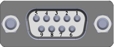
RS232 connector pinout
The RS232 connector type on this device is a DCE female. DCE stands for Data Communication Equipment.
| PIN |
NAME* |
DESCRIPTION* |
DIRECTION ON THIS DEVICE |
| 1 |
DCD |
Data Carrier Detect |
Output |
| 2 |
RXD |
Receive Data |
Output |
| 3 |
TXD |
Transmit Data |
Input |
| 4 |
DTR |
Data Terminal Ready |
Input |
| 5 |
GND |
Signal Ground |
- |
| 6 |
DSR |
Data Set Ready |
Output |
| 7 |
RTS |
Ready To Send |
Input |
| 8 |
CTS |
Clear To Send |
Output |
| 9 |
RI |
Ring Indicator |
Output (connected to +5V permanently via a 4.7k resistor) |
Cables
There are two types of RS232 serial devices: DTE and DCE. DTE typically refers to the serial port on a PC or terminal, while DCE refers to communication devices. Connectors mounted on DTE are likely to be male, and those mounted on DCE are likely to be female.
This device is DCE and has a female connector.
To connect a standard DTE device, use a straight-through Female/Male RS232 cable:
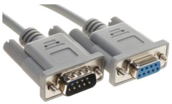
See straight cable pinout below:
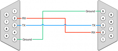
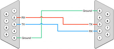
To connect another DCE device to RUT955, a Null-modem (crossed) Male/Male cable should be used:
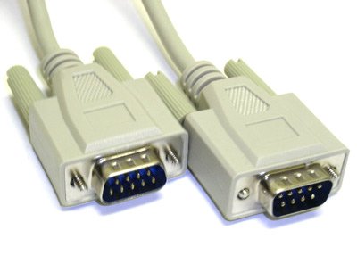
See straight crossed cable pinout below:
Maximum cable length is 15 meters or the cable length equal to a capacitance of 2500 pF (for a 19200 baud rate). Using lower capacitance cables can increase the distance. Reducing communication speed can also increase maximum cable length.
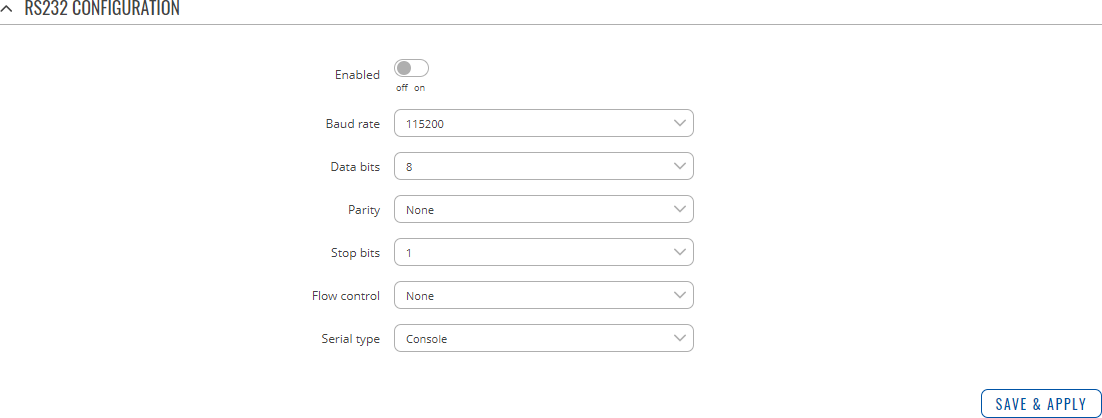
RS232 Configuration
The RS232 Configuration section is used to set up the main operating parameters and the serial type of the RS232 connector.
| Field |
Value |
Description |
| Enabled |
off | on; default: off |
Turns the RS232 service on or off. |
| Baud rate |
300 | 600 | 1200 | 2400 | 4800 | 9600 | 19200 | 38400 | 57600 | 115200; default: 115200 |
Data rate for serial data transmission (in bits per second (bps)). |
| Data bits |
5 | 6 | 7 | 8; default: 8 |
Number of data bits for each character. |
| Parity |
None | Odd | Even; default: None |
In serial transmission, parity is a method of detecting errors. An extra data bit is sent with each data character, arranged so that the number of 1 bits in each character, including the parity bit, is always odd or always even. If a byte is received with the wrong number of 1s, then it must have been corrupted. However, an even number of errors can pass the parity check.
- None (N) - no parity method is used.
- Odd (O) - the parity bit is set so that the number of "logical ones (1s)" has to be odd.
- Even (E) - the parity bit is set so that the number of "logical ones (1s)" has to be even.
|
| Stop bits |
1 | 2; default: 1 |
Stop bits sent at the end of every character allow the receiving signal hardware to detect the end of a character and to resynchronise with the character stream. Electronic devices usually use one stop bit. Two stop bits are required if slow electromechanical devices are used. |
| Flow control |
None | RTS/CTS | Xon/Xoff; default: None |
In many circumstances a transmitter might be able to send data faster than the receiver is able to process it. To cope with this, serial lines often incorporate a "handshaking" method, usually distinguished between hardware and software handshaking.
- RTS/CTS - hardware handshaking. RTS and CTS are turned OFF and ON from alternate ends to control data flow, for instance when a buffer is almost full.
- Xon/Xoff - software handshaking. The Xon and Xoff characters are sent by the receiver to the sender to control when the sender will send data, i.e., these characters go in the opposite direction to the data being sent. The circuit starts in the "sending allowed" state. When the receiver's buffers approach capacity, the receiver sends the Xoff character to tell the sender to stop sending data. Later, after the receiver has emptied its buffers, it sends an Xon character to tell the sender to resume transmission.
|
| Serial type |
Console | Over IP | Modem | Modbus gateway; default: Console |
Specifies the serial connection type.
Look to the sections below for information on different RS232 serial type options. |
Console
Console mode requires no further configuration than the settings above and is used as a direct-access method to the device's shell interface. For this purpose you may want use such applications as PuTTY on Windows and microcom, minicom, picocom or similar applications on Linux.

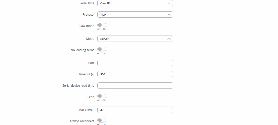
Over IP
The Over IP serial type is used to manage serial connections over a TCP/IP network.
| Field |
Value |
Description |
| Protocol |
TCP | UDP; default: TCP |
Protocol used in the communication process. |
| Raw mode |
off | on; default; default: off |
When enabled, all data will be transmitted transparently. |
| Mode |
Server | Client | Bidirect; default: Server |
This device's role in the connection:
- Server - the device waits for incoming connections.
- Client - the device initiates the connection.
- Bidirect - acts as client by default but waits for incoming connections at the same time.
|
| No leading zeros |
off | on; default: off |
When checked, indicates that the first hex zeros should be skipped. |
| Server settings: Port |
integer [0..65535]; default: none |
Internal port number used to listen for incoming connections. |
| Server settings | TCP: Timeout (s) |
integer [0..32767]; default: 300 |
Specifies an inactivity time limit (in seconds) after which an inactive clients is disconnected. |
| Bidirect: Output | Output (4) | Isolated Output (3,4,8) | Relay (5,10); default: Output (4) |
Specifies which output to manage. |
| Bidirect: Output state |
0 | 1; default: 0 |
Default output state value, when the application is started. |
| Server settings | UDP: Number of clients |
1-10; default: 1 |
Specifies how many UDP clients will be supported simultaneously (predefined clients does not count towards this limit). |
| Server settings | UDP: Predefined client 1 address |
ip4; default: none |
Specifies IP address for predefined connection 1. |
| Server settings | UDP: Predefined port 1 |
port; default: none |
Specifies port number for predefined connection 1. |
| Server settings | UDP: Predefined client 2 address |
ip4; default: none |
Specifies IP address for predefined connection 2. |
| Server settings | UDP: Predefined port 2 |
port; default: none |
Specifies port number for predefined connection 2. |
| Client settings: Server Address |
ip | host; default: none |
IP address or hostname of the server that this client will connect to. |
| Client settings: Port |
integer [0..65535]; default: none |
Server's listening port number. |
| Client settings: Reconnect interval (s) |
integer; default: none |
Time period (in seconds) between reconnection attempts in case a connection fails. |
| Serial device read time |
integer [0..1000]; default: none |
Specifies custom read time for the serial device. |
| Echo |
off | on; default: off |
Turns RS232 echo on or off. RS232 echo is a loopback test usually used to check whether the RS232 cable is working properly. |
| Server settings | TCP: Max clients |
integer [1..32]; default: 32 |
Specifies how many clients are allowed to connect simultaneously. |
| TCP: Always reconnect |
off | on; default: off |
When enabled, a new TCP connection will be made after sending every data package. |
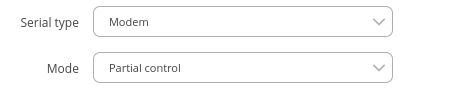
Modem
The Modem serial type is used to manage modem functionality which could be accessed using shell interface. For this purpose you may want use such applications with CR/LF (Carriage Return, Line Feed) capable applications like PuTTY on Windows and microcom, minicom, cutecom or similar applications on Linux.
| Field |
Value |
Description |
| Mode |
Partial control | Full control; default: Partial control |
Specifies modem control mode.
- Partial control- enables modem control with AT commands, mobile connection will be controlled by RUTOS.
- Full control- enables modem control with AT commands, mobile connection will be controlled by user.
|
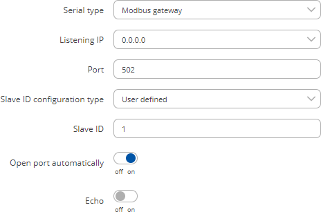
Modbus gateway
The Modbus gateway serial type allows redirecting TCP data coming to a specified port to an RTU specified by the Slave ID. The Slave ID can be specified by the user or be obtained directly from the Modbus header.
| Field |
Value |
Description |
| Listening IP |
ip; default: 0.0.0.0 |
IP address to listen for incoming connections. The default value (0.0.0.0) means that this device will listen for incoming connections on any interface or IP address. |
| Port |
integer [0..65535]; default: 502 |
Port number to listen for incoming connections. |
| Slave ID configuration type |
User defined | Obtained from TCP;
default: User defined |
Specifies whether slave IDs are user defined or automatically obtained from TCP. |
| Slave ID | Permitted slave IDs |
integer | range of integers;
default: 1 or 1-247 |
Specifies the slave ID of range of permitted slave IDs. The way this field is named and its function depends on the value of the Slave ID configuration field.
A range of IDs can be specified by placing a hyphen (-) between two integer numbers. For example, if you permit slave IDs in the range of 10 to 20, you would specify it as: 10-20
You can also specify multiple values that are not connected in a range using commas (,). For example, to specify 6, 50 and 100 as permitted slave IDs, you would have to use: 6,50,100 |
| Open port automatically |
off | on; default: on |
Automatically adds a traffic rule in the firewall configuration to open the required port for serial communication.
Caution: use with care if listening IP is left as the default value (0.0.0.0). Leaving it as such will leave the device open for remote connections on the specified port. |
| Echo |
off | on; default: off |
Turns RS232 echo on or off. RS232 echo is a loopback test usually used to check whether the RS232 cable is working properly. |
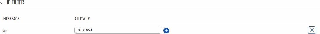
IP Filter
The IP Filter section is used for configuring which network is allowed to communicate with the device. You may add a new instance by selecting the Interface and pressing Add.
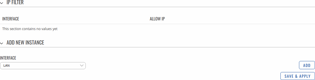
Then enter the IP address and save.