
QSG OTD500
This Wiki page contains the online version of the Quick Start Guide (QSG) for the OTD500 Outdoor Router. Here you will find an overview of the various components on the front and back of a OTD500 device, hardware installation instructions, first login information, device specifications, and general safety information. It is highly recommended to acquaint yourself with the Quick Start Guide before using the device. You can also locate a printed version of the Quick Start Guide in the packaging box of your device.
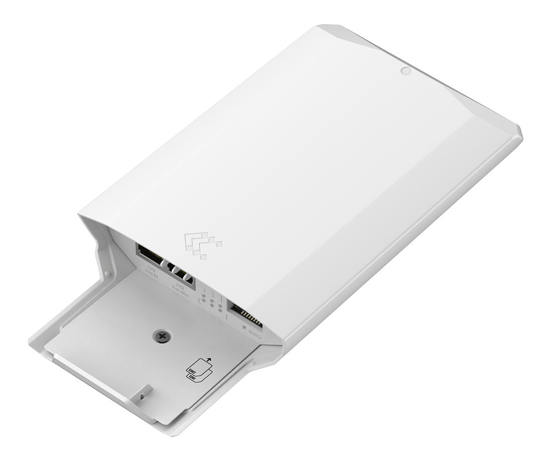 |
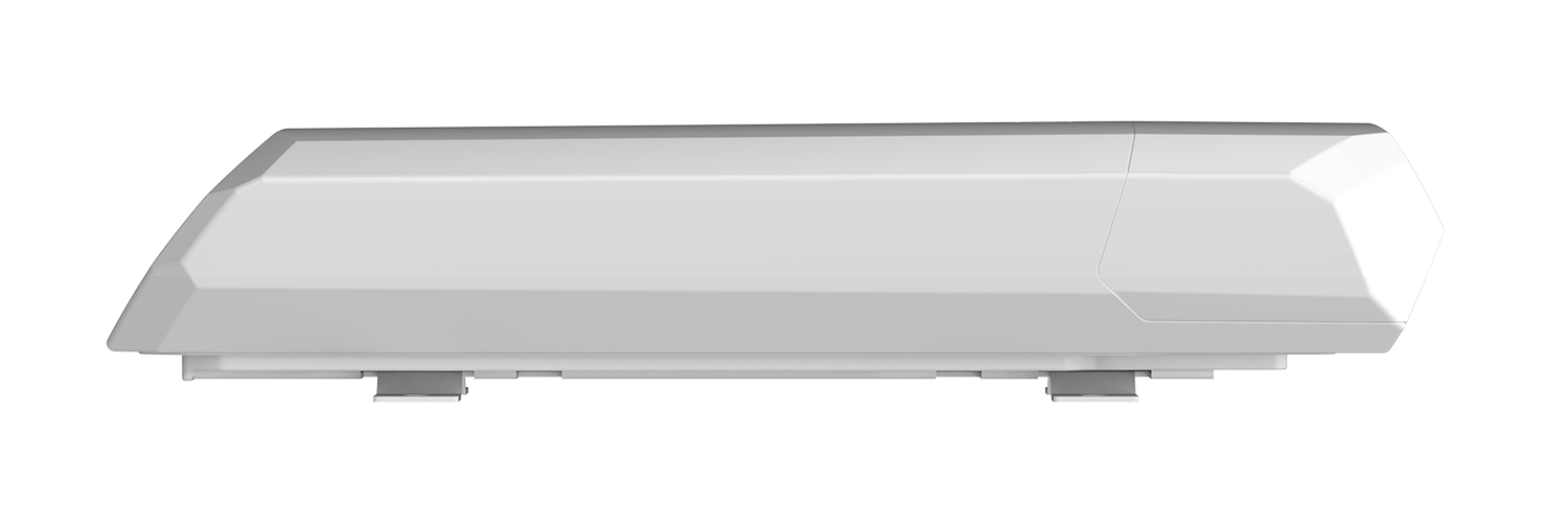 |
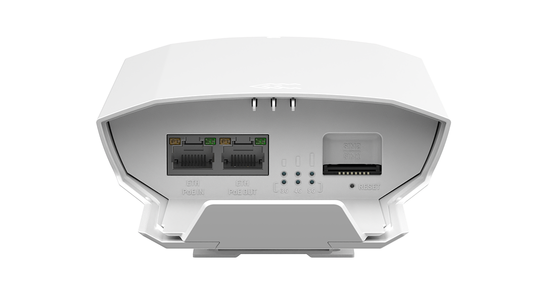 |
Safety information
Before starting operating the device, please review recommendations and precautions to minimize the possibility of accidents. Safety precautions presented are supplementary and subject to the local safety regulations. When various operations are executed on the device, the user must fully follow the safety instructions and recommendations provided with the device.
General
| Technical specifications | |
|---|---|
| Input voltage range | 42.5–57.0 VDC, reverse polarity protection, voltage surge/transient protection |
| Radio specifications | |
| RF technologies | 3G, 4G, 5G |
| Max RF power | 25dBm@WCDMA, 28dBm@LTE, 28dBm@5G |
| Integrated antennas specifications | |
| Mobile antennas | internal - 4 x 617 - 960/1695 - 2690/3300 - 4200/4200 - 5000MHz, 50 Ω, VSWR <3.5, gain <4.9 dBi, omnidirectional |
* Order code dependant.
OTD500 outdoor router must be used in compliance with any and all applicable national and international laws and with any special restrictions regulating the utilization of the communication module in prescribed applications and environments.
PoE standards
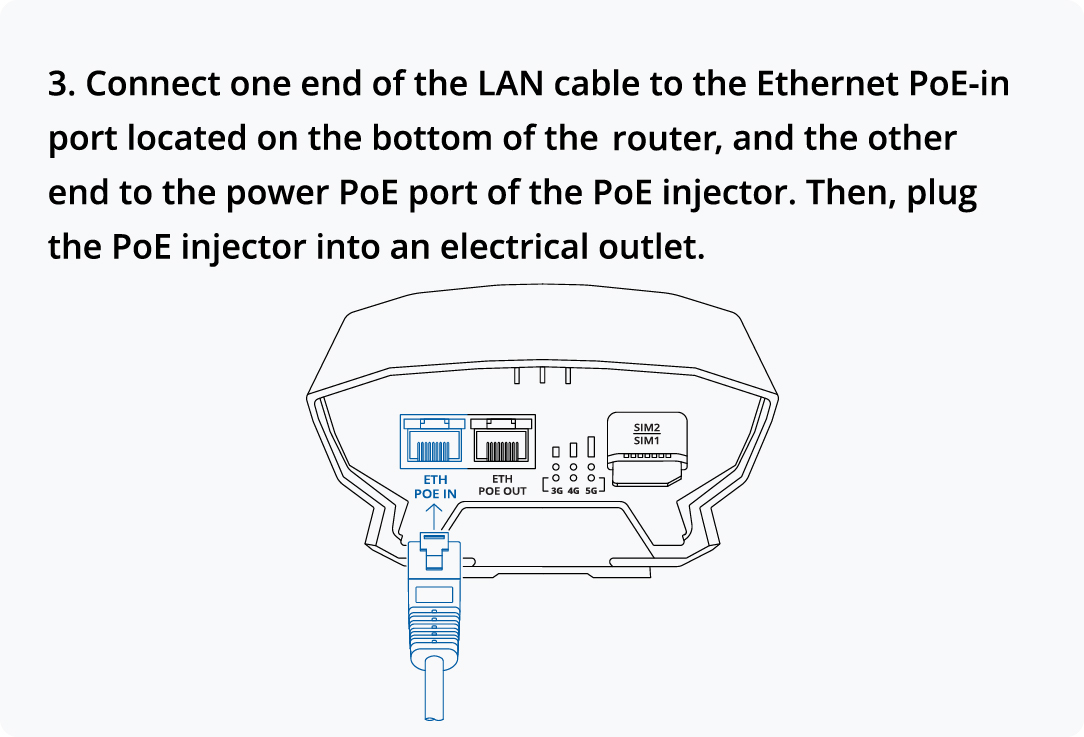
This device uses PoE alternative B.
The difference between PoE alternative A and alternative B
Alternative A:
802.3af and 802.3at Alternative A connection. The power sourcing equipment applies a positive voltage to pins 1-2 and a negative voltage to pins 3-6.
| Pins at switch | T568A Color | T568B Color | 10/100 Alternative A, mixed DC & data | 1000 (1 gigabit) Alternative A, DC & bi-data | ||
| Pin 1 |  white/green stripe |
 white/orange stripe |
Rx + | DC + | TxRx A + | DC + |
| Pin 2 |  green solid |
 orange solid |
Rx − | DC + | TxRx A − | DC + |
| Pin 3 | white/orange stripe |
white/green stripe |
Tx + | DC − | TxRx B + | DC − |
| Pin 4 |  blue solid |
Unused | Unused | TxRx C + | |
| Pin 5 |  white/blue stripe |
Unused | Unused | TxRx C - | |
| Pin 6 | orange solid |
green solid |
Tx − | DC − | TxRx B − | DC − |
| Pin 7 |  white/brown stripe |
Unused | Unused | TxRx D + | |
| Pin 8 |  brown solid |
Unused | Unused | TxRx D - | |
Alternative B:
802.3af and 802.3at Alternative B connection. The power sourcing equipment applies a positive voltage to pins 4-5 and a negative voltage to pins 7-8.
| Pins at switch | T568A Color | T568B Color | 10/100 Alternative B, DC on spares | 1000 (1 gigabit) Alternative B, DC & bi-data | ||
| Pin 1 | white/green stripe |
white/orange stripe |
Rx + | TxRx A + | ||
| Pin 2 | green solid |
orange solid |
Rx − | TxRx A − | ||
| Pin 3 | white/orange stripe |
white/green stripe |
Tx + | TxRx B + | ||
| Pin 4 | blue solid |
blue solid |
DC + | TxRx C + | DC + | |
| Pin 5 | white/blue stripe |
white/blue stripe |
DC + | TxRx C - | DC + | |
| Pin 6 | orange solid |
green solid |
Tx − | TxRx B − | ||
| Pin 7 | white/brown stripe |
white/brown stripe |
DC − | TxRx D + | DC − | |
| Pin 8 | brown solid |
brown solid |
DC − | TxRx D - | DC − | |
CE Declaration of Conformity
| [BG] Bulgarian | С настоящето, TELTONIKA NETWORKS декларира, че OTD500 е в съответствие със съществените изисквания и другитеприложими разпоредби на Директива 2014/53/EU |
| [HR] Croatian | Ovim TELTONIKA NETWORKS izjavljuje da je ovaj OTD500 u skladu s bitnim zahtjevima i ostalim relevantnim odredbama Direktive 2014/53/EU |
| [CZ] Czech | TELTONIKA NETWORKS tímto prohlašuje, že OTD500 splňuje základní požadavky a všechna příslušná ustanoveni Směrnice 2014/53/EU |
| [DK] Danish | Undertegnede TELTONIKA NETWORKS erklærer herved, at følgende udstyr OTD500 overholder de væsentlige krav og øvrige relevante krav i direktiv 2014/53/EU |
| [NL] Dutch | Hierbij verklaart TELTONIKA NETWORKS dat het toestel I OTD500 in overeenstemming is met de essentiële eisen en de andere relevante bepalingen van richtlijn 2014/53/EU |
| [EE] Estonian | Käesolevaga kinnitab TELTONIKA NETWORKS seadme OTD500 vastavust direktiivi 2014/53/EU põhinõuetele ja nimetatud direktiivist tulenevatele teistele asjakohastele sätetele |
| [FI] Finish | TELTONIKA NETWORKS vakuuttaa täten että OTD500 tyyppinen laite on direktiivin 2014/53/EU oleellisten vaatimusten ja sitä koskevien direktiivin muiden ehtojen mukainen |
| [FR] French | TELTONIKA NETWORKS déclare que cette OTD500 est conforme aux exigences essentielles et aux autres dispositions pertinentes de la directive 2014/53/EU |
| [DE] German | Hiermit erklärt TELTONIKA NETWORKS, dass dieser OTD500 den grundlegenden Anforderungen und anderen relevanten Bestimmungen der Richtlinie 2014/53/EU entspricht |
| [GR] Greek | ΜΕ ΤΗΝ ΠΑΡΟΥΣΑ Ο ΚΑΤΑΣΚΕΥΑΣΤΗΣ TELTONIKA NETWORKS ΔΗΛΩΝΕΙ ΟΤΙ OTD500 ΣΥΜΜΟΡΦΩΝΕΤΑΙ ΠΡΟΣ ΤΙΣ ΟΥΣΙΩΔΕΙΣ ΑΠΑΙΤΗΣΕΙΣ ΚΑΙ ΤΙΣ ΛΟΙΠΕΣ ΣΧΕΤΙΚΕΣ ΔΙΑΤΑΞΕΙΣ ΤΗΣ ΟΔΗΓΙΑΣ 2014/53/EU |
| [HU] Hungarian | A TELTONIKA NETWORKS ezzennel kijelenti, hogy a OTD500 típusú berendezés teljesíti az alapvető követelményeket és más 2014/53/EU irányelvben meghatározott vonatkozó rendelkezéseket |
| [IE] Irish | Leis seo, dearbhaíonn TELTONIKA NETWORKS go gcomhlíonann an OTD500 seo bunriachtanais agus forálacha ábhartha eile Threoir 2014/53/EU |
| [IT] Italian | Con la presente, TELTONIKA NETWORKS dichiara che questo OTD500 è conforme ai requisiti essenziali e ad altre disposizioni pertinenti della Direttiva 2014/53/EU |
| [LV] Latvian | Ar šo TELTONIKA NETWORKS deklarē, ka OTD500 atbilst Direktīvas 2014/53/EU būtiskajām prasībām un citiem ar to saistītajiem noteikumiem |
| [LT] Lithuanian | Šiuo dokumentu UAB TELTONIKA NETWORKS deklaruoja, kad šis OTD500 atitinka esminius reikalavimus ir kitas 2014/53/EU Direktyvos nuostatas |
| [MT] Maltese | Hawnhekk, TELTONIKA NETWORKS tiddikjara li dan l-OTD500 huwa konformi mar-rekwiżiti essenzjali u dispożizzjonijiet rilevanti oħra tad Direttiva 2014/53/EU |
| [NO] Norwegian | TELTONIKA NETWORKS Erklærer herved at OTD500 er i samsvar med de grunnleggende krav og øvrige relevante krav i direktiv 2014/53/EU |
| [PL] Polish | Niniejszym TELTONIKA NETWORKS deklaruje że OTD500 jest zgodny z zasadniczymi wymaganiami i innymi właściwymi postanowieniami Dyrektywy 2014/53/EU |
| [PT] Portuguese | Eu, TELTONIKA NETWORKS declaro que o OTD500 cumpre os requisitos essenciais e outras provisões relevantes da Directiva 2014/53/EU |
| [RO] Romanian | Prin prezenta, TELTONIKA NETWORKS declară că aparatul OTD500 este în conformitate cu cerinţele esenţiale şi cu alte prevederi pertinente ale Directivei 2014/53/EU |
| [SK] Slovak | Spoločnosť TELTONIKA NETWORKS týmto vyhlasuje, že smerovač OTD500 je v súlade so základnými požiadavkami a ďalšími príslušnými ustanoveniami smernice 2014/53/EU |
| [SI] Slovenian | TELTONIKA NETWORKS izjavlja, da je ta OTD500 v skladu z bistvenimi zahtevami in drugimi relevantnimi določili direktive 2014/53/EU |
| [ES] Spanish | Por la presente, TELTONIKA NETWORKS declara que este OTD500 cumple con los requisitos esenciales y otras exigencias relevantes de la Directiva 2014/53/EU |
| [SE] Swedish | Härmed intygar TELTONIKA NETWORKS att denna OTD500 är i överensstämmelse med de väsentliga egenskapskrav och övriga relevanta bestämmelser som framgår av direktiv 2014/53/EU |
Detailed compliance information is available at the following internet address: wiki.teltonika-networks.com/view/Certificates.
 This sign means that is necessary to read the User's Manual before you start using the device.
 This sign on the package means that all used electronic and electric equipment should not be mixed with general household waste.
 Hereby, TELTONIKA NETWORKS declares that this OTD500 is in compliance with the essential requirements and other relevant provisions of Directive 2014/53/EU. The full text of the EU declaration of conformity is available at the following internet address: https://wiki.teltonika-networks.com/view/OTD500_CE/RED.
 Hereby, TELTONIKA NETWORKS declares that the radio equipment type OTD500 is in compliance with Radio Equipment Regulations 2017. The full text of the UK declaration of conformity is available at the following internet address: https://wiki.teltonika-networks.com/view/OTD500_UKCA.
RF exposure
This device meets the official requirements for exposure to radio waves. This device is designed and manufactured not to exceed the emission limits for exposure to radio frequency (RF) energy set by authorized agencies. The device must be used with a minimum separation of 20 cm from a person’s body to ensure compliance with RF exposure guidelines. Failure to observe these instructions could result in your RF exposure exceeding the applicable limits.
External antennas used with OTD500 must be installed to provide a distance of at least 20 cm from any people and must not be co-located or operated in conjunction with any other antenna or transmitter.
Any external antenna gain must meet RF exposure and maximum radiated output power limits of the applicable rule section.
| Operating Frequency / Maximum transmission power | ||
|---|---|---|
| WCDMA | B1 | 1920-1980, 2110-2170 MHz, 25 dBm |
| B51 | 824-849, 869-894 MHz, 25 dBm | |
| B8 | 880-915, 925-960 MHz, 25 dBm | |
| LTE-FDD | B1 | 1920-1980, 2110-2170 MHz, 25 dBm |
| B3 | 1710-1785, 1805-1880 MHz, 25 dBm | |
| B51 | 824-849, 869-894 MHz, 25 dBm | |
| B7 | 2500-2570, 2620-2690 MHz, 25 dBm | |
| B8 | 880-915, 925-960 MHz, 25 dBm | |
| B20 | 832-862, 791-821 MHz, 25 dBm | |
| B28 | 703-748, 758-803 MHz, 25 dBm | |
| LTE-TDD | B38 | 2570-2620 MHz, 28 dBm |
| B40 | 2300-2400 MHz, 28 dBm | |
| B412 | 2496-2690 MHz, 28 dBm | |
| B422 | 3400-3600 MHz, 28 dBm | |
| B432 | 3600-3800 MHz, 28 dBm | |
| 5G NR (SA, NSA) | n1 | 1920-1680, 2110-2170 MHz, 25 dBm |
| n3 | 1710-1785, 1805-1880 MHz, 25 dBm | |
| n51 | 824-849, 869-894 MHz, 25 dBm | |
| n7 | 2500-2570, 2620-2690 MHz, 25 dBm | |
| n8 | 880-915, 925-960 MHz, 25 dBm | |
| n20 | 832-862, 791-821 MHz, 25 dBm | |
| n28 | 703-748, 758-803 MHz, 25 dBm | |
| n38 | 2570-2620 MHz, 25 dBm | |
| n40 | 2300-2400 MHz, 25 dBm | |
| n41 | 2496-2690 MHz, 28 dBm | |
| n77 | 3300-4200 MHz, 28 dBm | |
| n78 | 3300-3800 MHz, 28 dBm | |
1 – Not supported in Europe region.
2 – Not supported in Europe and Oceania regions.
 In all EU member states, operation of 5150-5350 MHz is restricted to indoor use only.
Operating conditions
- Operating temperature: -40° to +75° Celsius
- Humidity should be in the range of 10% to 90% (non-condensing).
- Away from heat source, corrosive substances, salts, and flammable gases
Attention: operation outside the permissible range can considerably shorten the service life of the device.
Faulty and damaged products
- Do not attempt to disassemble the device or its accessories.
- Only qualified personnel must service or repair the device or its accessories.
- If your device or its accessories have been submerged in water punctured or subjected to a severe fall, do not use until they have been checked at an authorized service center.
Electrical safety
- Only use approved accessories.
- Do not connect with incompatible products or accessories.
- It is recommended to ground devices with grounding terminals before connecting them to power. Failure to ground appropriately might result in a shock hazard. The cross-sectional area of the protective grounding conductor should be at least 1mm2.
Product handling
- You alone are responsible for how you use your device and any consequences related to its use.
- Use of your device is subject to safety measures designed to protect users and their environment.
- Always treat your device and its accessories with care.
- Do not expose your device or its accessories to open flames, lit tobacco products, liquid, or high humidity.
- Do not drop, throw or try to bend your device or its accessories.
- Do not use harsh chemicals, cleaning solvents, or aerosols to clean the device or its accessories.
- Do not paint your device or its accessories.
- Do not attempt to disassemble your device (exemptions for devices that require disassembly for SIM insertion) or its accessories: it does not contain any user-serviceable parts. For safety reasons, the equipment should be opened only by qualified personnel.
- Make sure to use ESD personal protective equipment while the equipment is serviced.
- Do not use your device in an enclosed environment where heat dissipation is poor.
- Prolonged use in such space may cause excessive heat and raise ambient temperature, which will lead to the automatic shutdown of your device or the disconnection of the mobile network connection for your safety. To use your device again after such a shutdown, cool it in a well-ventilated place before turning it on.
- Please check all national laws and local regulations for the disposal of electronic products.
- Do not operate the device where ventilation is restricted.
- Do not use or install this product near water to avoid fire or shock hazards.
- Arrange power and Ethernet cables so that they are not likely to be stepped on or have items placed on them.
- Ensure that the voltage and the rated current of the power source match the device’s requirements. Do not connect the device to an inappropriate power source.
- During a thunderstorm, no operations should be carried out on the device and cables.
- The unit must be powered off where blasting is in progress and explosive atmospheres are present or near medical life support equipment.
- Do not leave your device and its accessories within reach of small children or allow them to play with it. They could hurt themselves or others and could accidentally damage the device. Your device contains small parts with sharp edges that may cause an injury choking hazard.
- Like any wireless device, this device operates using radio signals, which cannot guarantee connection in all conditions. Therefore, you must never rely solely on any wireless device for emergency communications or otherwise use the device in situations where the interruption of data connectivity could lead to death, personal injury, property damage, data, or other loss.
- The device may become warm during regular use.
Front view
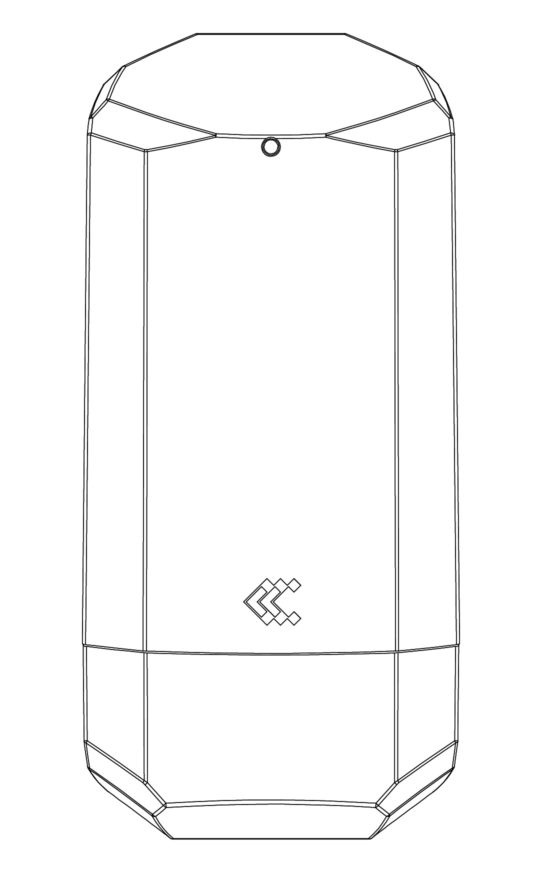
Back view
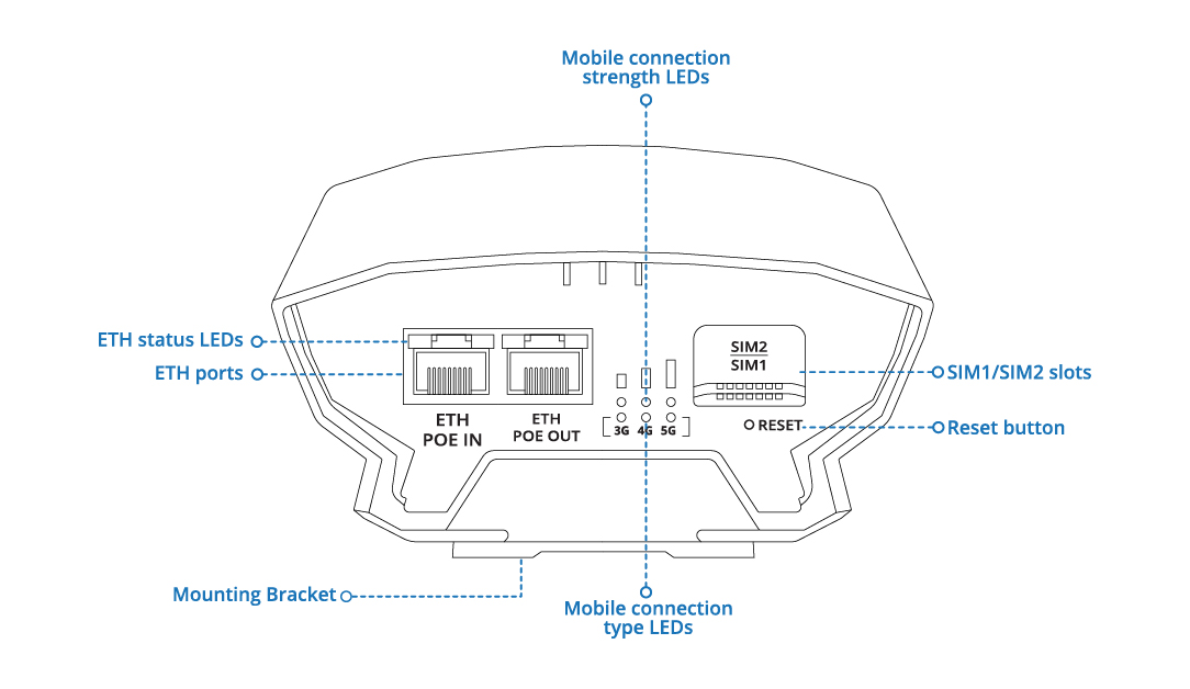
OTD500 ETH Ports
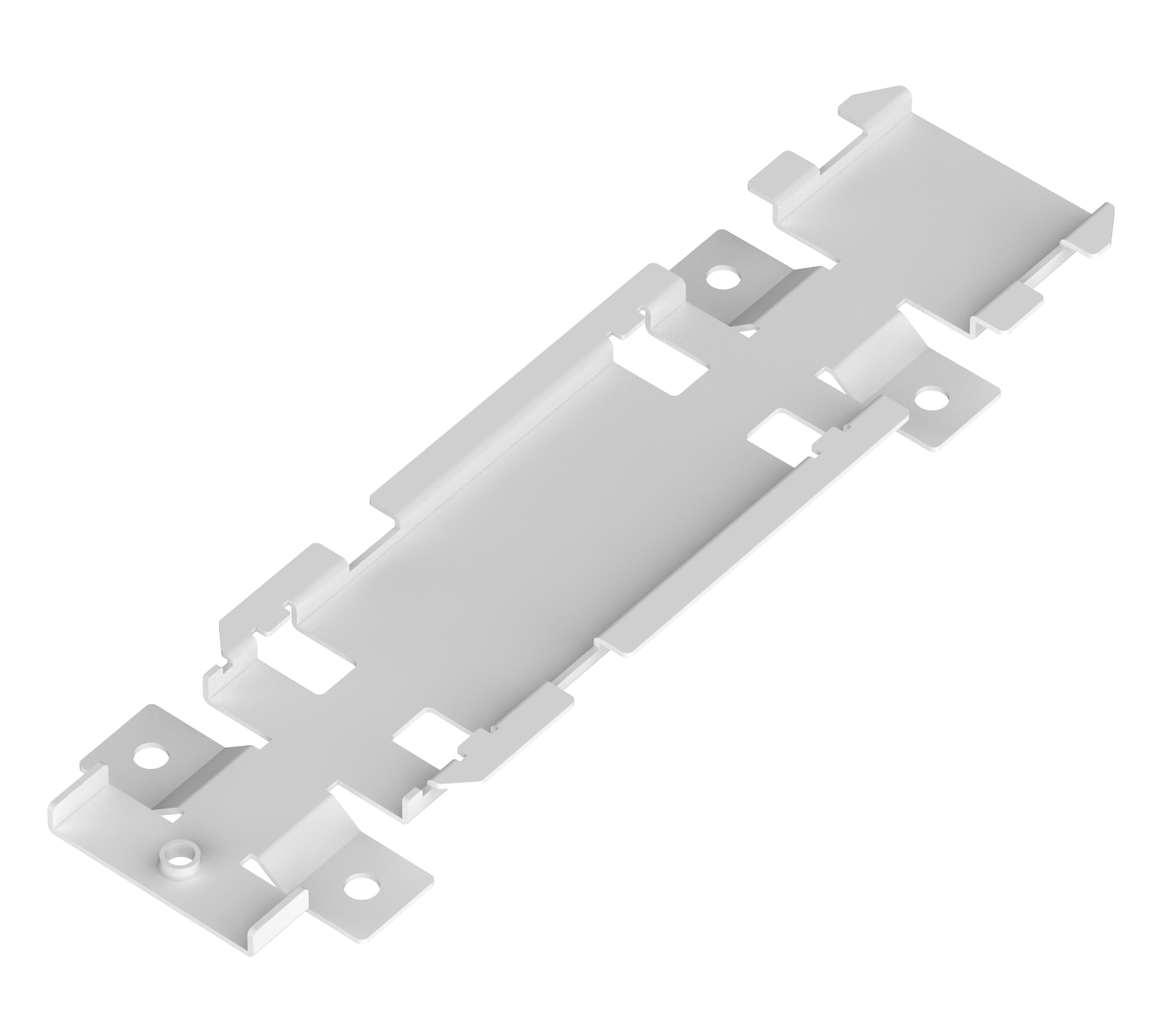
OTD500 Mounting Bracket
 |
eSIM
The Mobile eSIM feature on OTD500 eSIM devices allows users to manage eSIM profiles, configure settings, and use enhanced network capabilities. For more information please refer to the OTD500 eSIM manual.
- eSIM Profiles - You can easily add new eSIM profiles or configure existing ones. This section details profile management, including editing profile names and activation codes.
- SIM Switch - The SIM Switch provides you with the possibility to configure SIM switching rules, i.e., set up circumstances under which the device will perform a switch from using one SIM card to another.
- Multiwan - The Failover function allows you to backup your primary WAN connection in case it goes down.

To learn more about all the eSIM feature and its settings, please refer to the OTD500 eSIM manual.
Hardware installation
 |
 |
 |
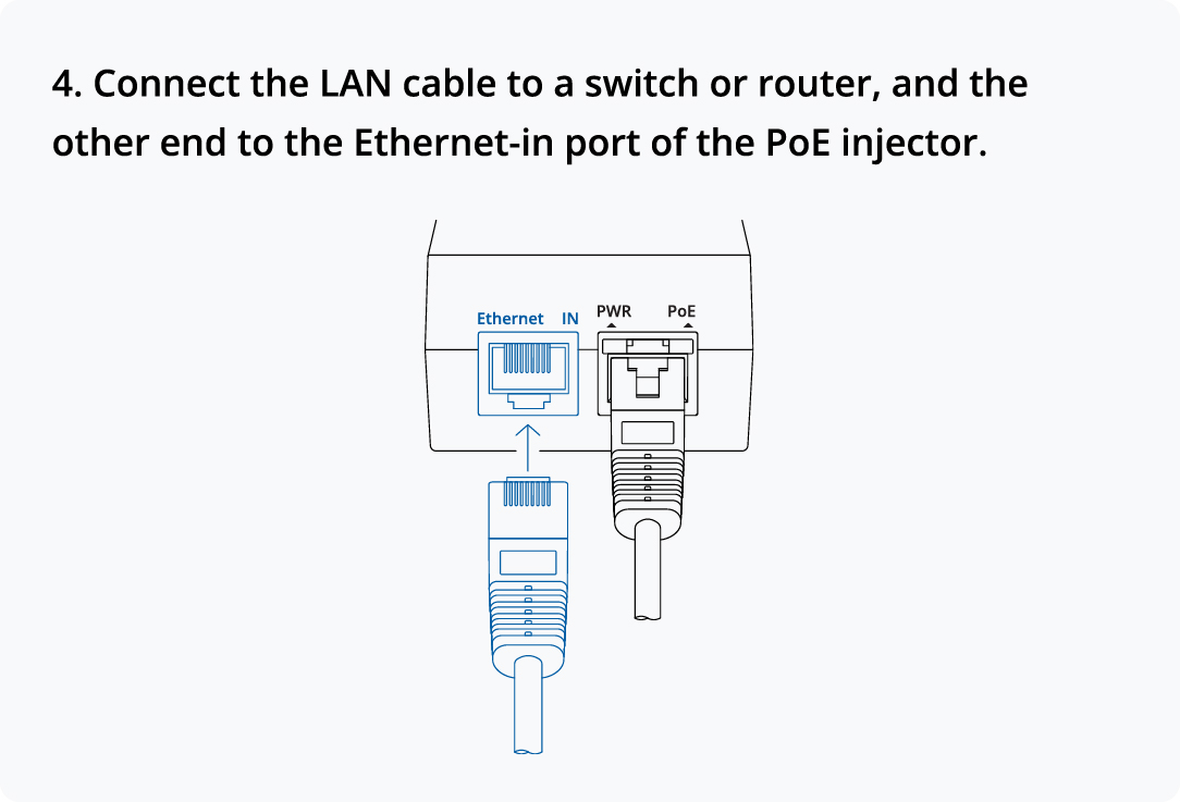 |
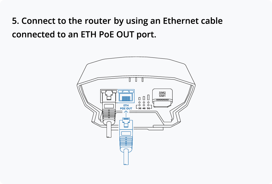 |
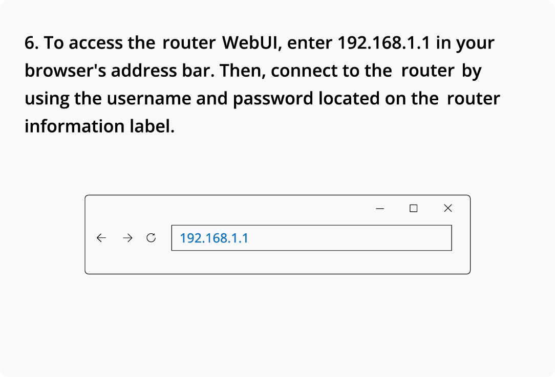 |
Configure your computer LAN (Windows)
| 1. Ensure the Network connection is Enabled. Go to Start — Control Panel — Network and Internet — Network and Sharing Center. Click on the Change adapter settings in the left panel, then right-click on Network Adapter, and select Enable. |  |
| 2. Check if IP and DNS are obtained automatically. Right-click on Network Adapter and select Properties. Then select Internet Protocol Version 4 and click Properties.
3. If not selected, check to obtain an IP address and obtain DNS server address automatically. Click OK. |
 |
Mounting instruction
Wall Mounting
1. The tools and fasteners required for installing the OTD500 depend on the type of wall surface and the chosen fasteners. To secure the OTD500's's housing onto the bracket, you will need a screwdriver, ideally one with a PZ2 nozzle. 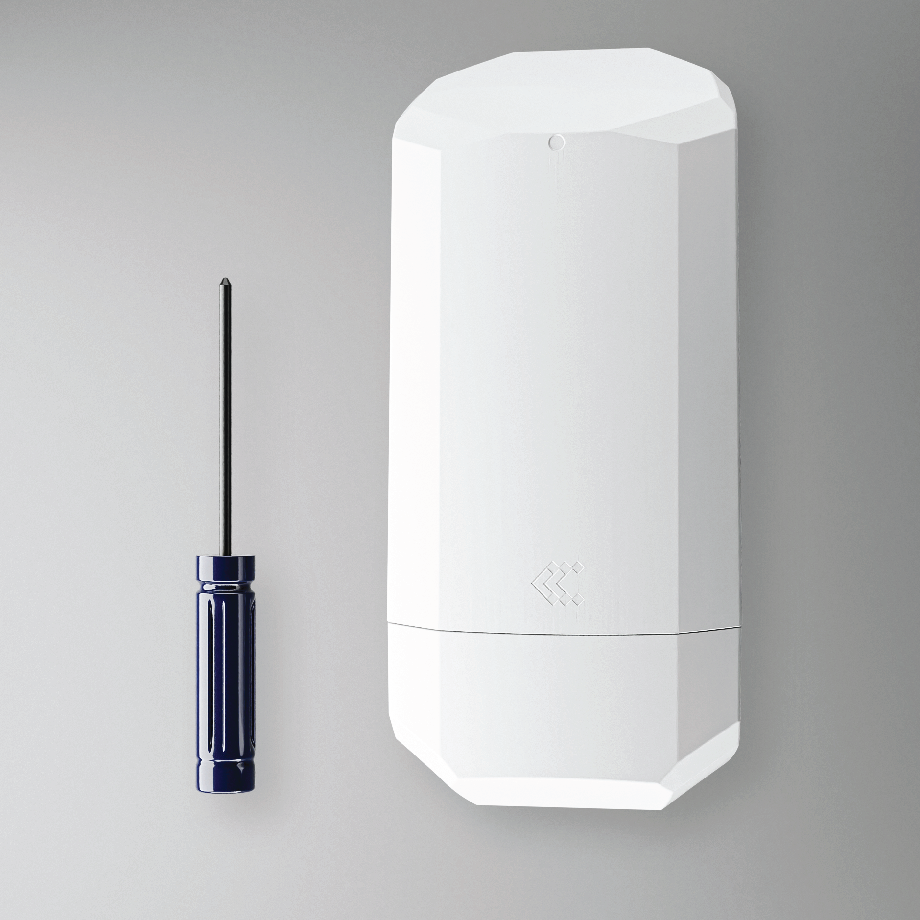 |
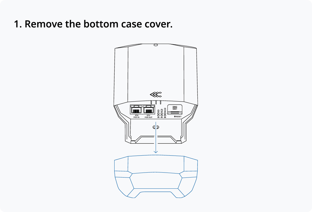
2. Remove the bottom part of the OTD140's and remove the bracket by unscrewing the screws.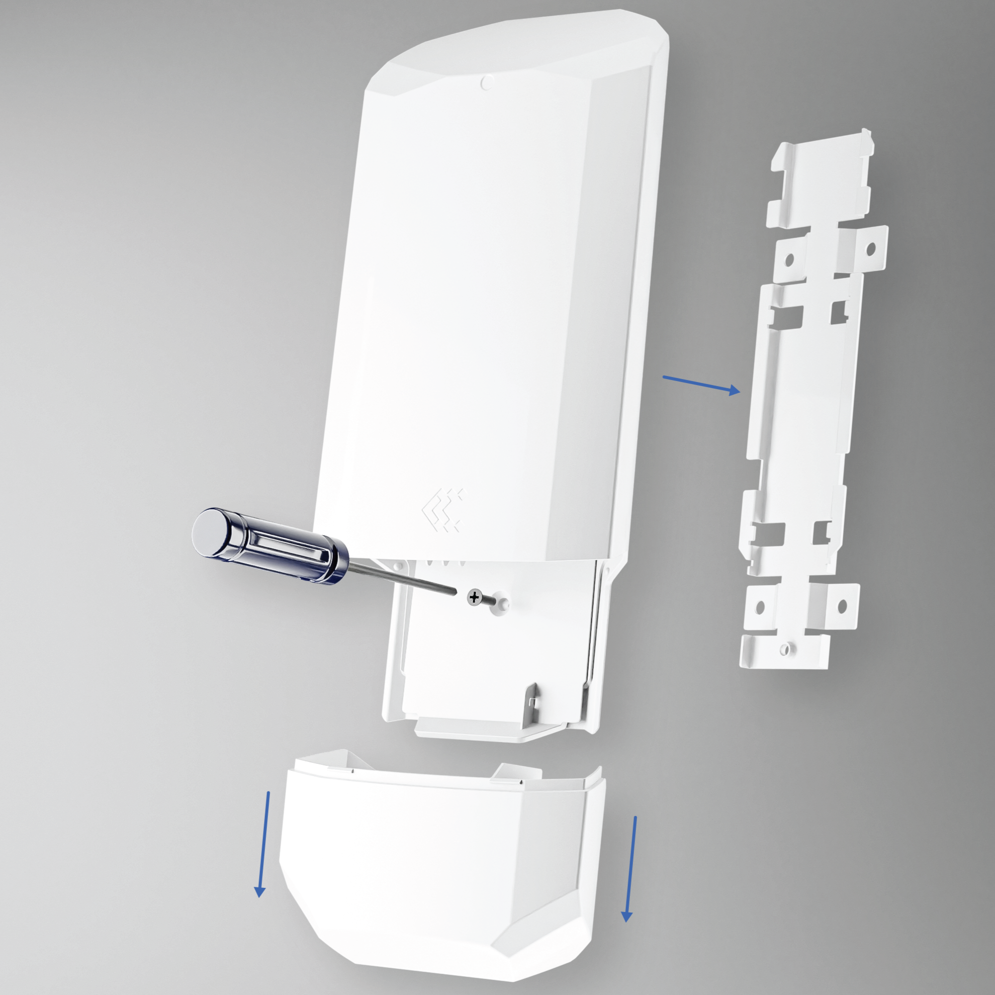 |
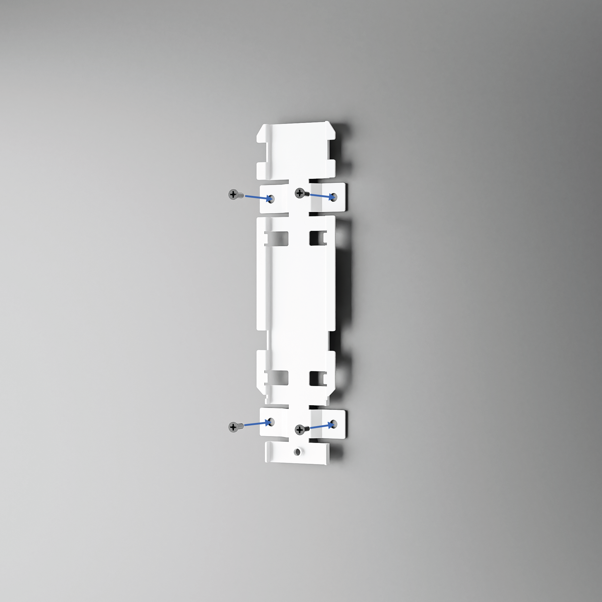
3. The bracket should be attached to the wall using screws fitting for the type of wall surface. The diameter of the holes should be 4.8 mm, or about 0.19 inches.
 |
4. Align the OTD500 with the bracket and press it downward until the OTD500's housing is locked into place on the bracket. This locking should close a gap of about 10 mm, or 0.39 inches. |
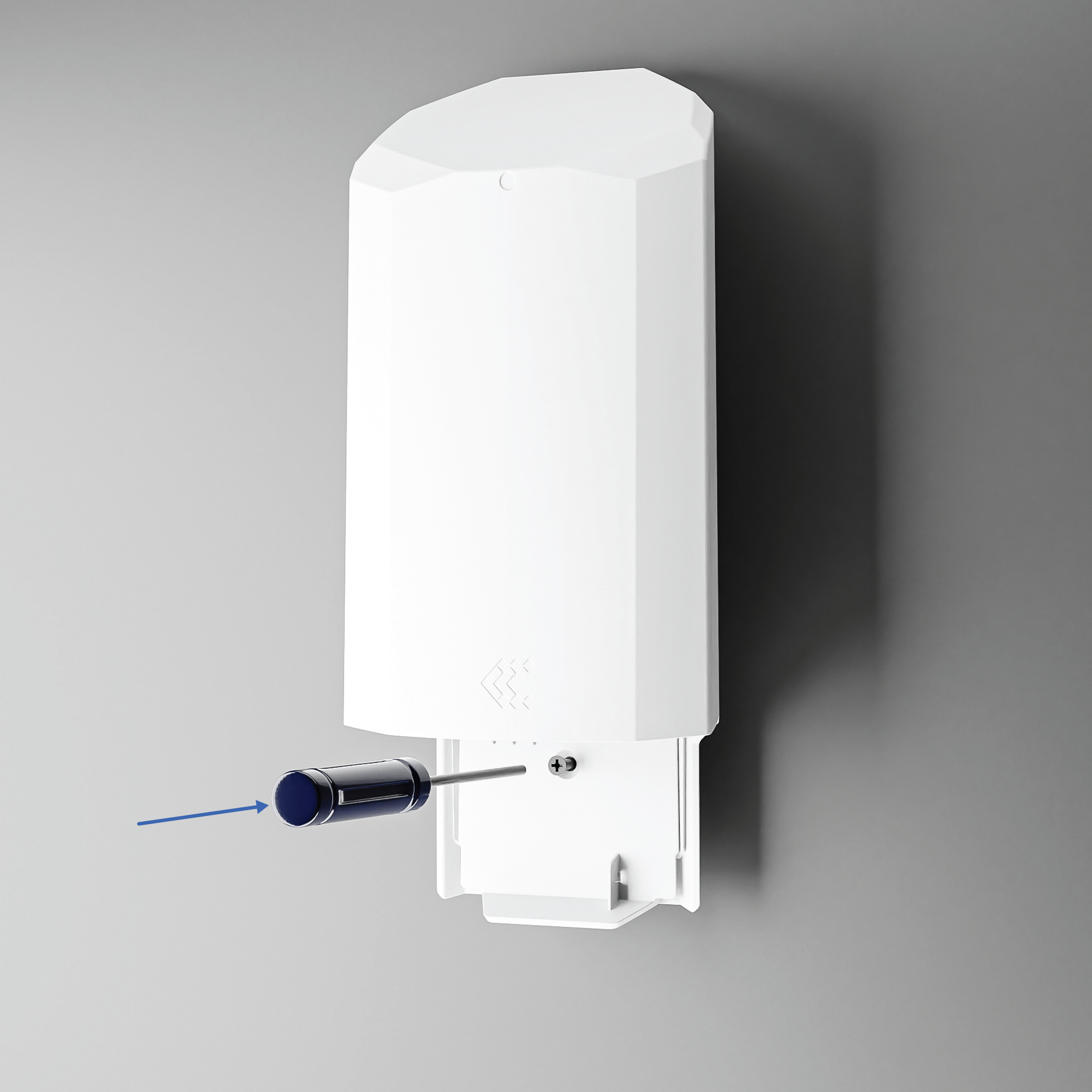
5. Insert and tighten the screw provided in the kit to secure the locked housing to the bracket.
 |
6. Finally, attach the bottom part of the OTD500's housing to the bottom of the mounted router.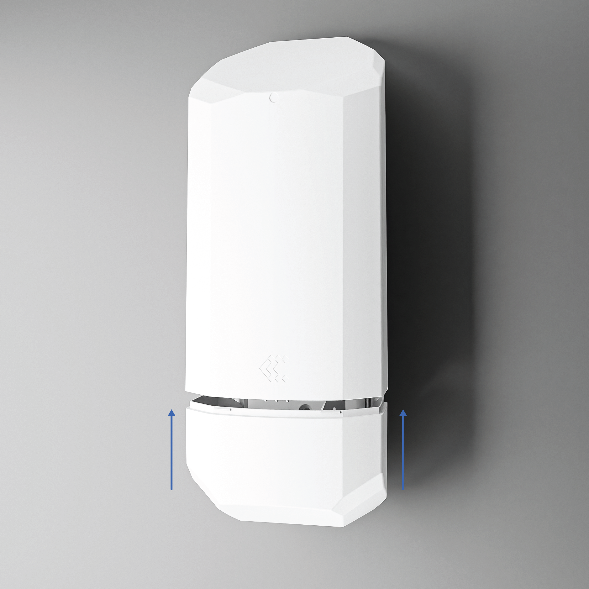 |
Pole Mounting
1. It is recommended to install the OTD on a pole at least 45 mm, or about 1.77 inches, in diameter. Ensure the chosen pole can support the weight of the product, which is 855 g. and you will need a screwdriver, ideally one with a PZ2 nozzle. 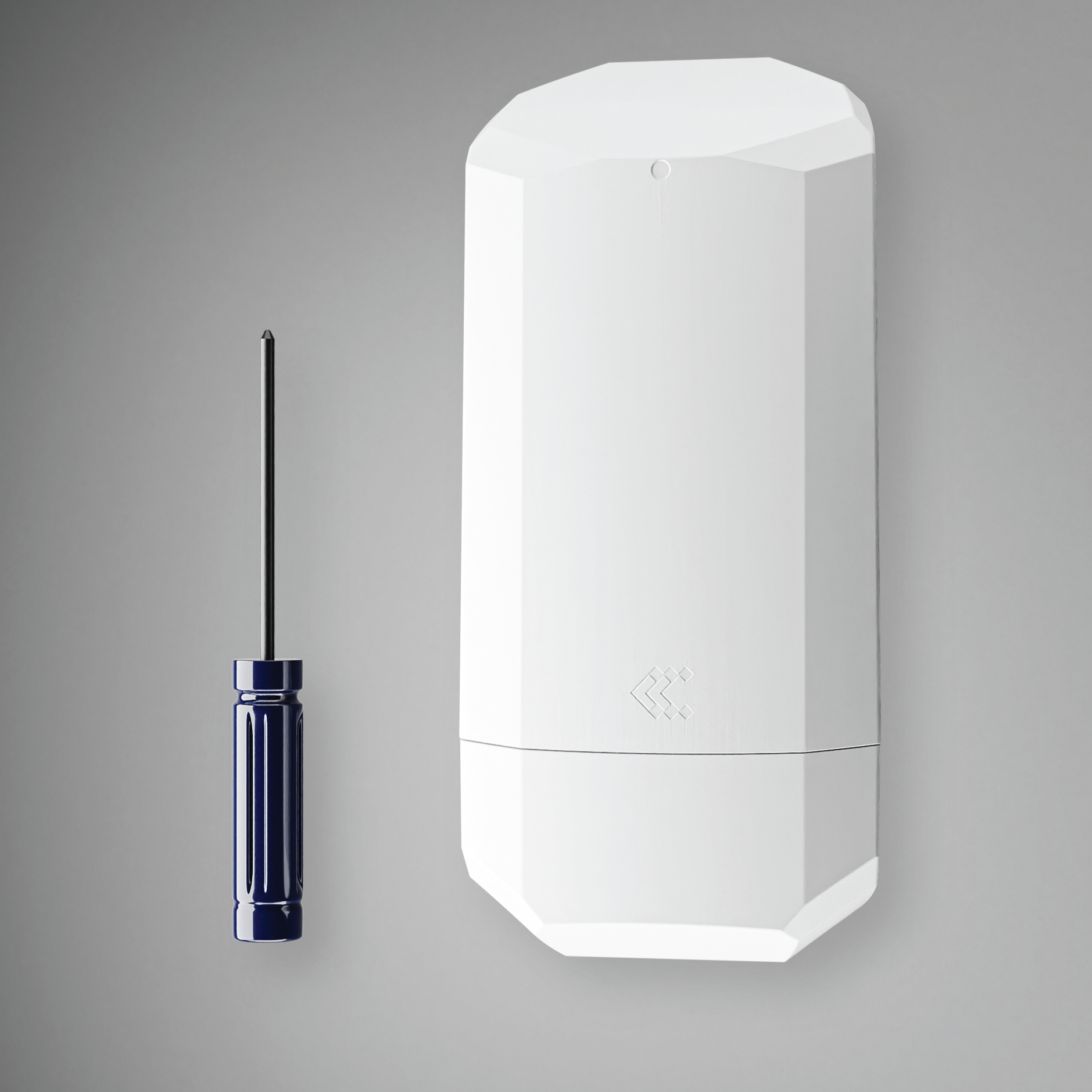 |
2. Remove the bottom part of the OTD500's and remove the bracket by unscrewing the screws. 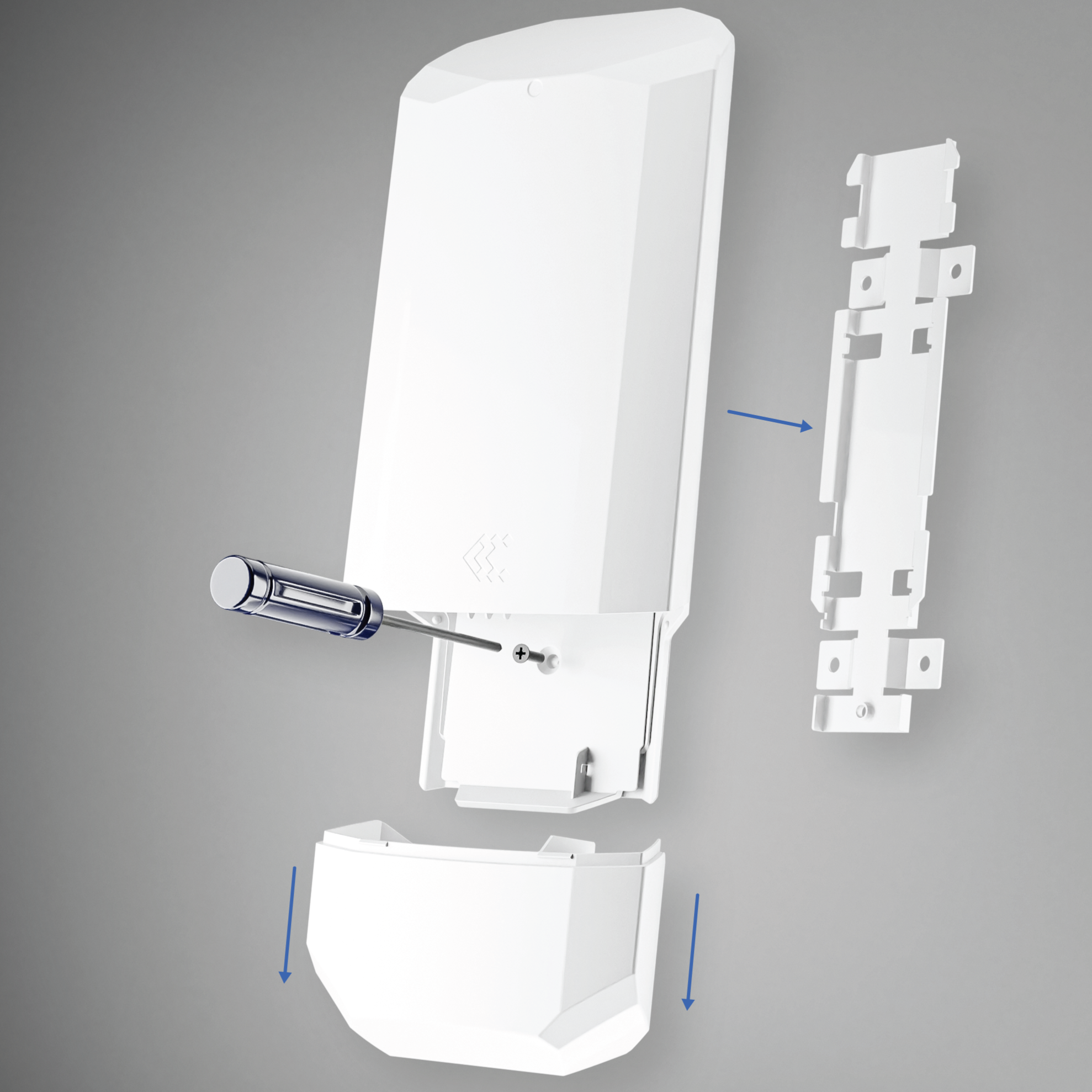 |
3. Select any of the bracket's holes to fit the width of the fastener, either a plastic zipper or a metal lintel. For plastic zippers, the diameter of the holes should be 4.8 mm, or about 0.31 inches. For metal lintel, it should be 8 mm, or about 0.31 inches. Note that product kit does not include any fasteners.
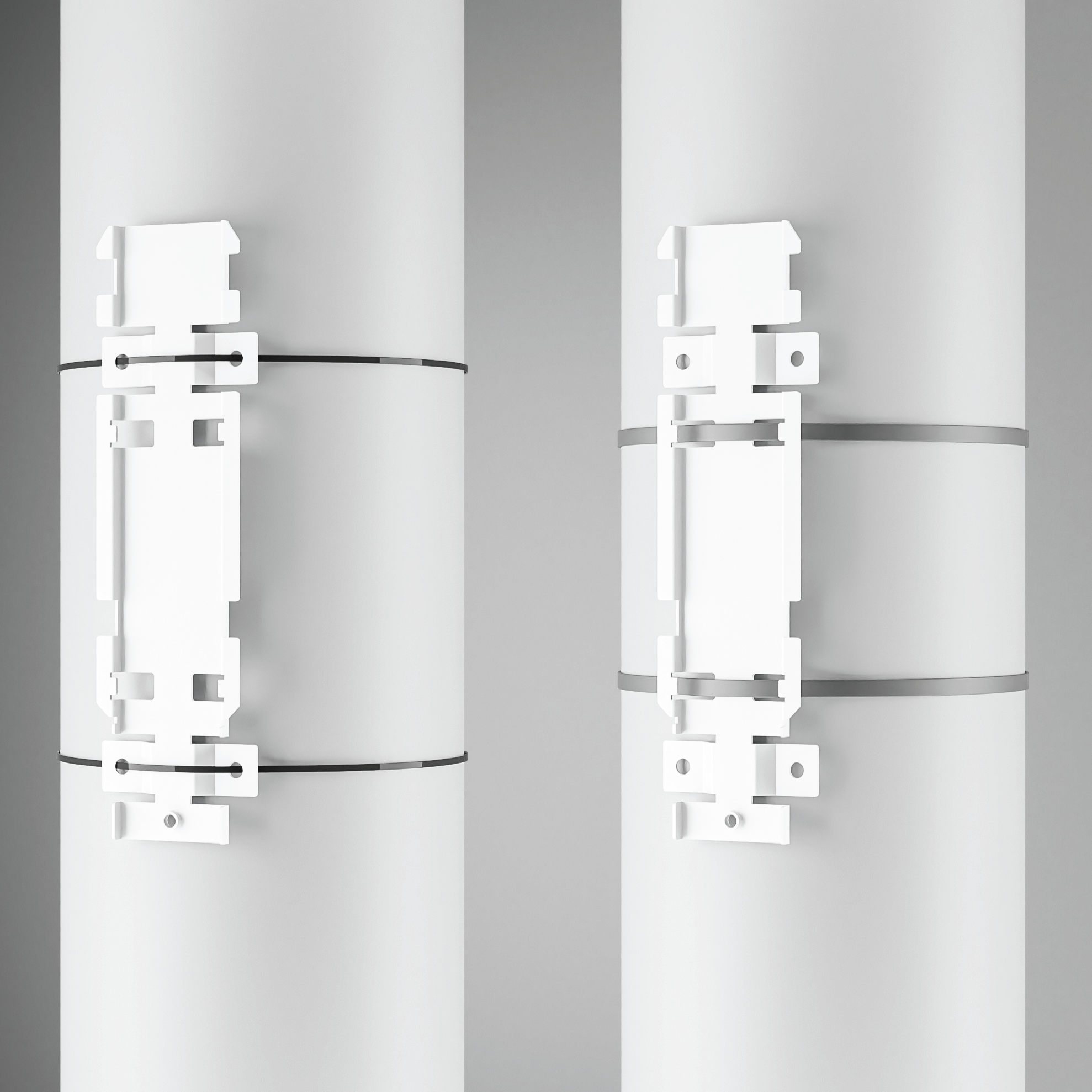 |
4. Align the OTD500 with the bracket and press it downward until the OTD500's housing is locked into place on the bracket. This locking should close a gap of about 10 mm, or 0.39 inches. 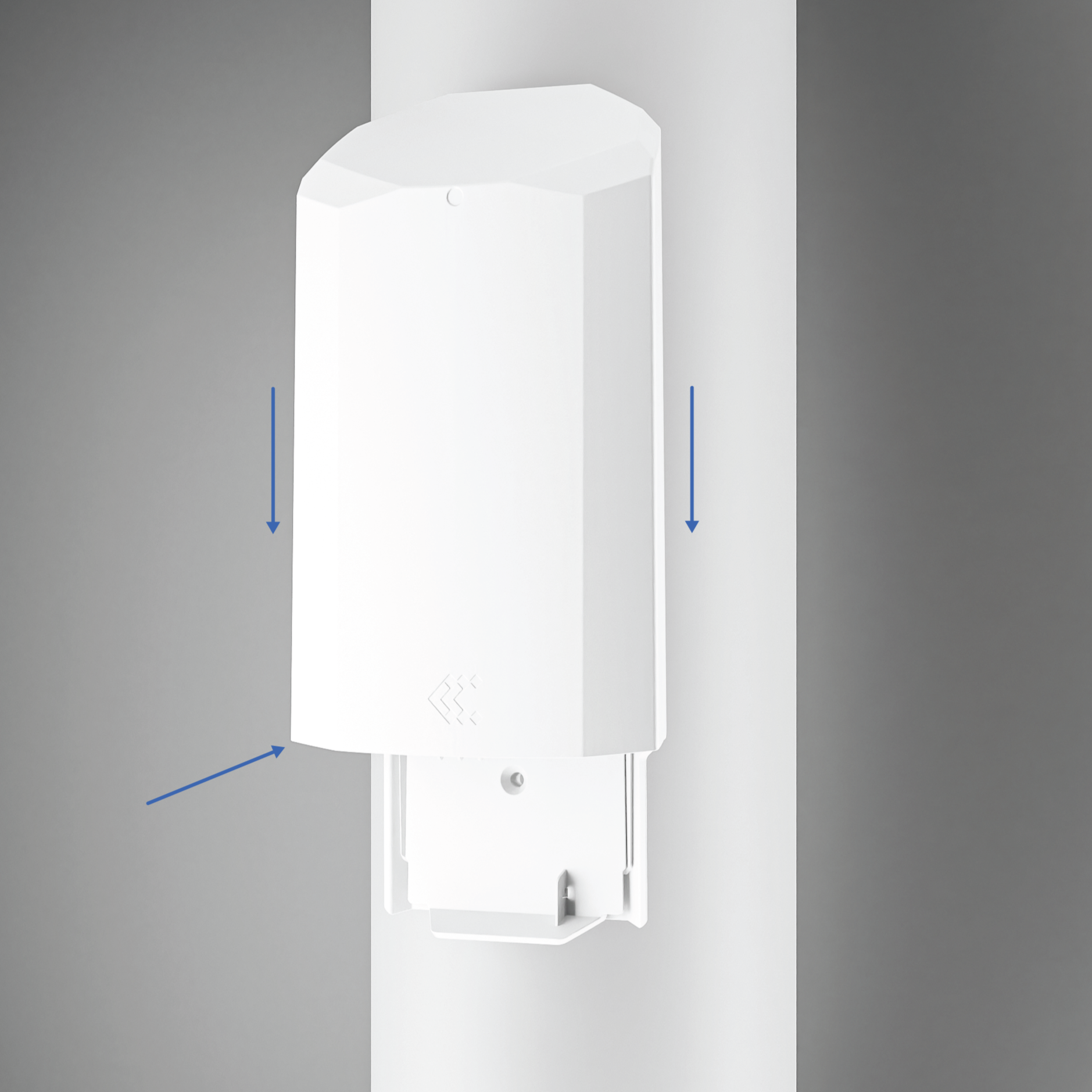 |
5. Insert and tighten the screw provided in the kit to secure the locked housing to the bracket.
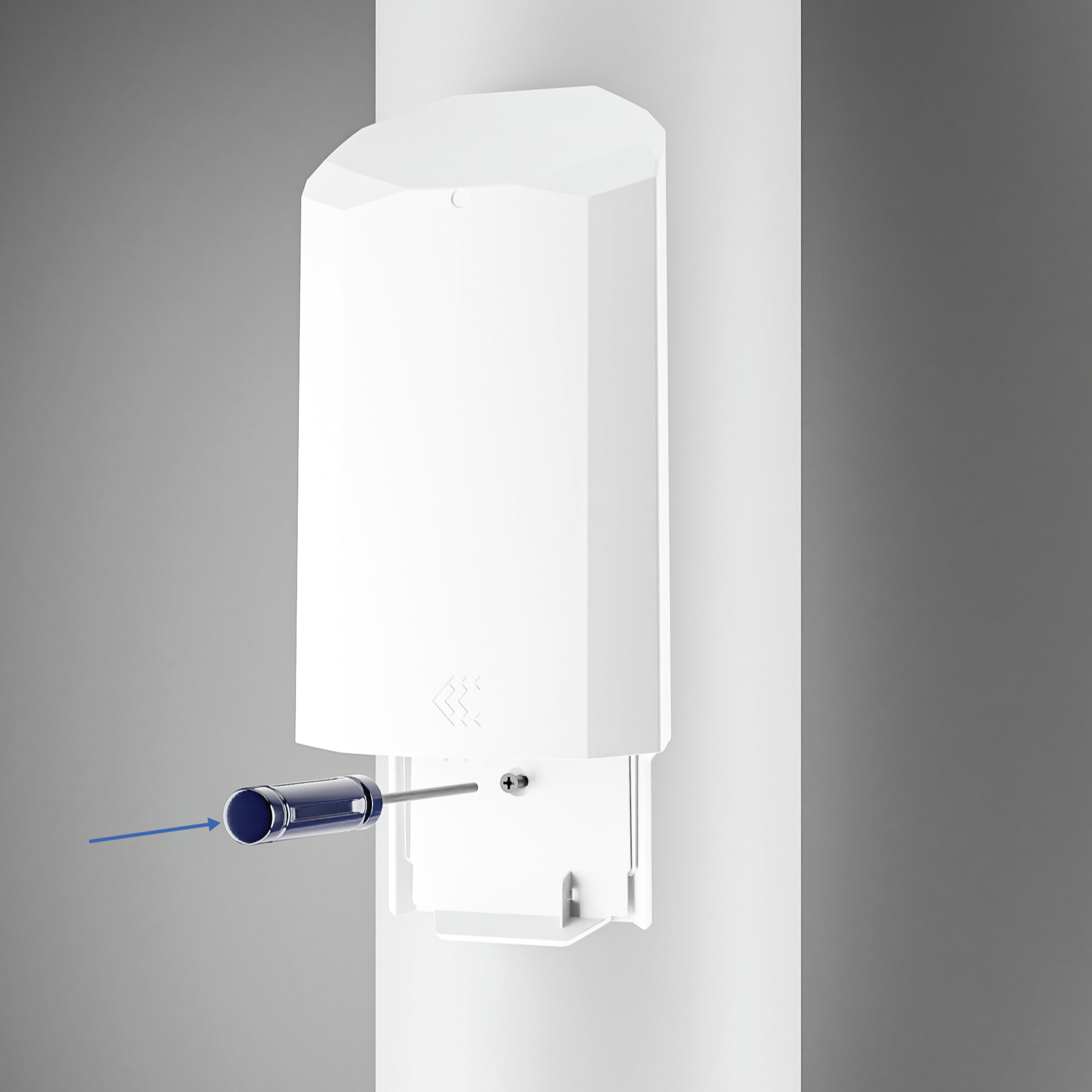 |
6. Finally, attach the bottom part of the OTD500's housing to the bottom of the mounted router. 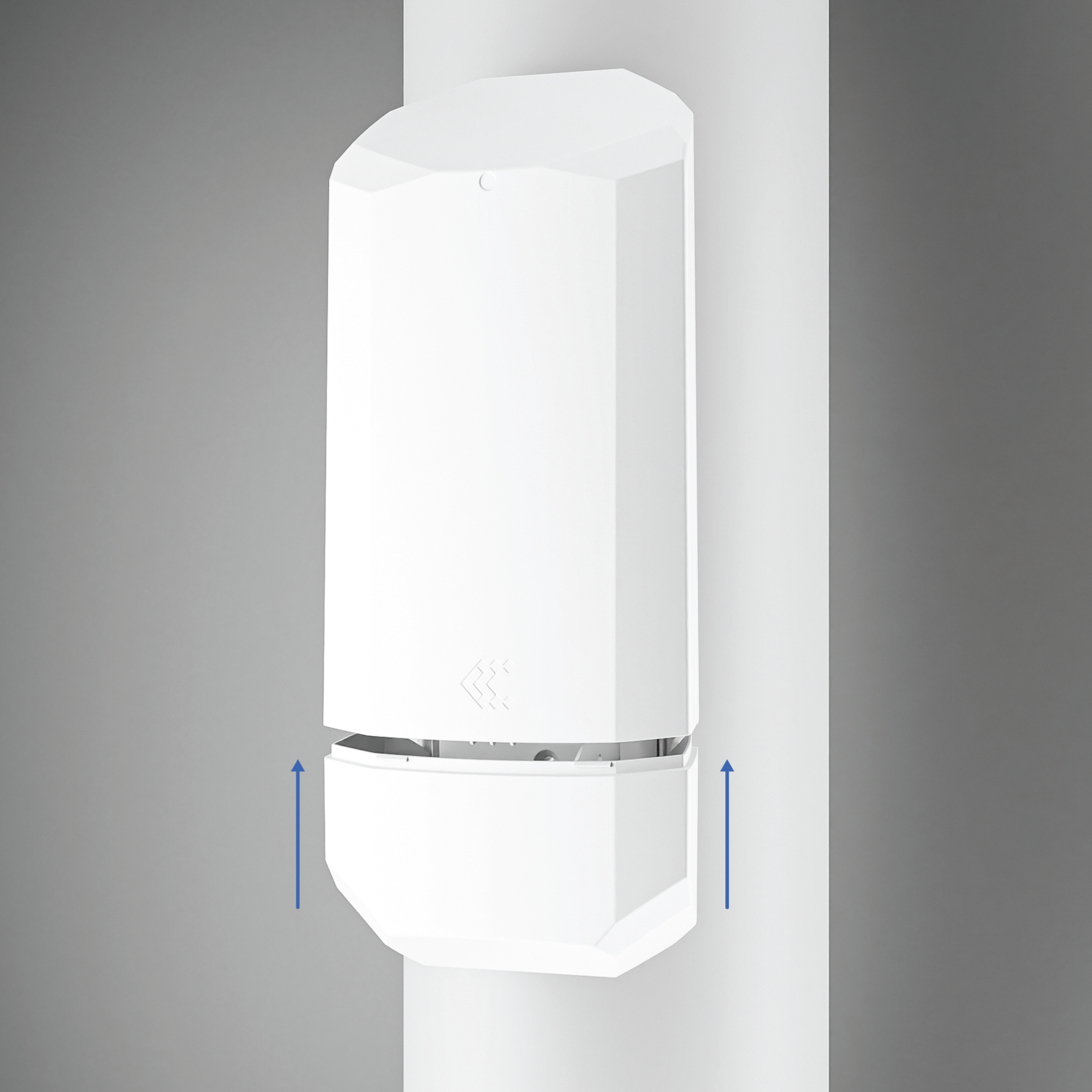 |
Login to device
| 1. To enter the router's Web interface (WebUI), type http://192.168.1.1 into the URL field of your Internet browser. 2. When prompted for authentication enter the username admin and enter the password located on the device information label/engraving. |
 |
| 3. After logging in, you must set a new password for security reasons. You will not be able to interact with the router’s WebUI until the default password is changed. The new password must consist of a minimum of 8 characters. Requirements: one uppercase letter, one lowercase letter, and one digit. 4. Next, the Configuration Wizard will start to help you set up some of the router's main operational parameters. |